Polygon mirror scanner motor

一种多角镜、扫描器的技术,应用在镜子、仪器、安装等方向,能够解决多角镜P变形等问题

Active Publication Date: 2018-10-23
MINEBEAMITSUMI INC
View PDF10 Cites 1 Cited by
  • Summary
  • Abstract
  • Description
  • Claims
  • Application Information

AI Technical Summary

Problems solved by technology

Therefore, there is a problem that the mirror fixing spring 505 bites into the polygon mirror P, and the polygon mirror P is easily deformed.

Method used


Image

  • Polygon mirror scanner motor
  • Polygon mirror scanner motor
  • Polygon mirror scanner motor

Examples


Embodiment Construction

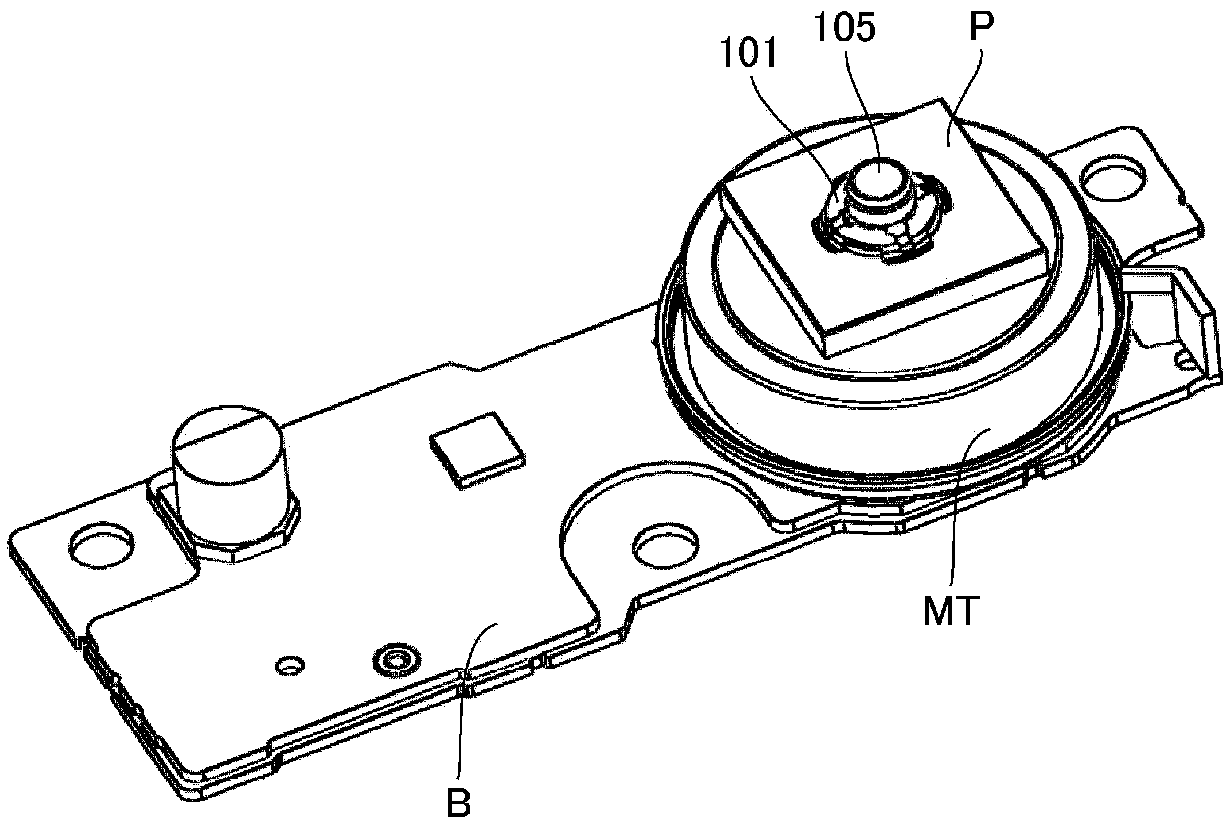
[0074] figure 1 It is a perspective view of a polygon mirror (polygon mirror) scanner motor in one embodiment of the present invention.

[0075] As shown in the figure, the polygon mirror scanner motor includes: a base part B on which a control circuit is formed, a motor MT, a sleeve 105 mounted on the rotating shaft of the motor MT, and a polygon mirror mounted on the supporting surface of the sleeve 105. The mirror P, and the mirror fixing spring 101 that presses the polygon mirror P from above to the supporting surface.

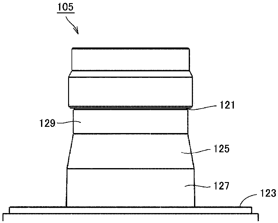
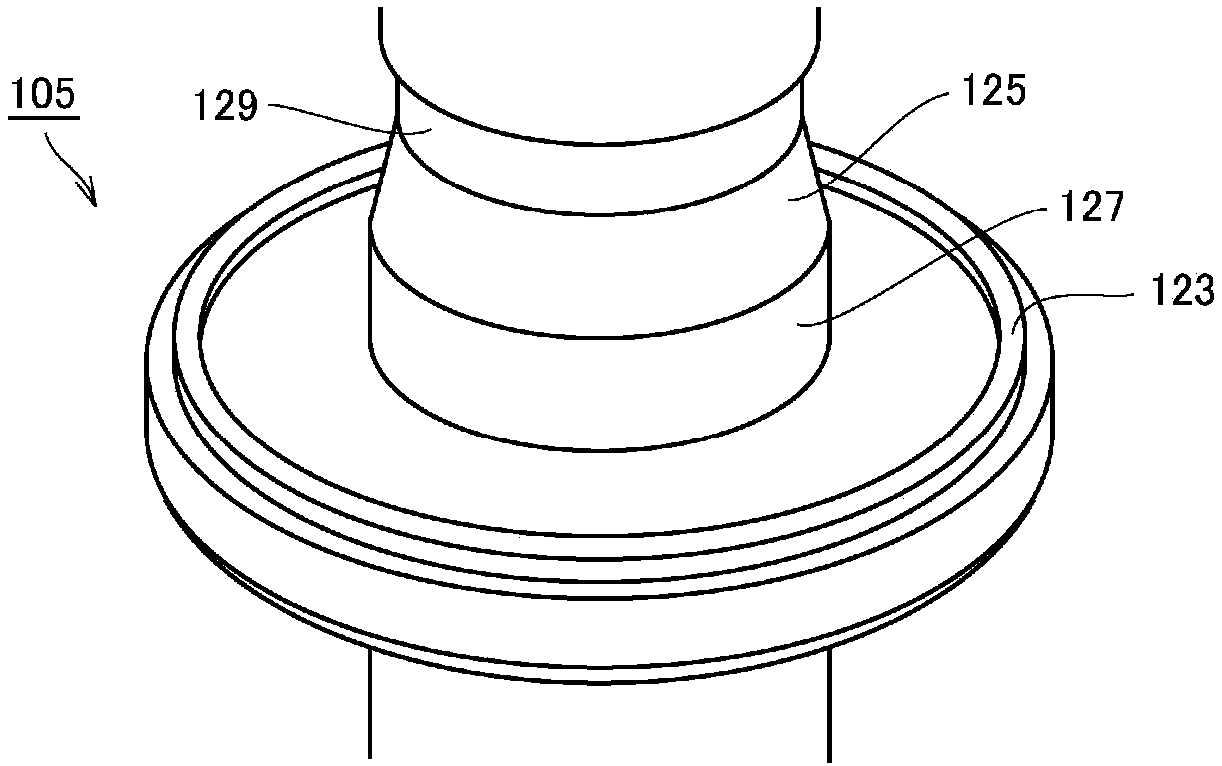
[0076] figure 2 yes figure 1 Side view of the sleeve 105 of the polygon mirror scanner motor. image 3 from an oblique view figure 1 Perspective view of a portion of the sleeve 105 of the polygon mirror scanner motor. Figure 4 from oblique view figure 1 Perspective view of a portion of the sleeve 105 of the polygon mirror scanner motor. Figure 5 is used for figure 1 The perspective cross-sectional view illustrating the construction of the s...


PUM


Abstract

The invention provides a polygon mirror scanner motor to which a polygon mirror can be attached with excellent precision. A distance between a motor rotary shaft and the pressurizing position of the polygon mirror (P) by a mirror fixing spring (101) is shorter than a distance between the motor rotary shaft and a position at which the polygon mirror (P) comes into contact with a seat surface (123).When a difference between an outer radius and an inner radius of the polygon mirror (P) is defined as A, and a distance, in a direction orthogonal to the motor rotary shaft, between the pressurizingposition of the mirror fixing spring (101) and the position of the seat surface (123) is defined as C, the relationship of 0<C< / =A / 4 is established. When a distance, in a direction orthogonal to the motor rotary shaft, between an inner diameter position of the polygon mirror (P) and the position of the seat surface (123) is defined as E, the relationship of A / 3< / =E< / =A / 2 is established.

Description

technical field [0001] The invention relates to a polygon mirror scanner motor, in particular to a polygon mirror scanner motor in which a polygon mirror is fixed by a mirror fixing spring. Background technique [0002] In laser writing systems such as laser printers, polygon mirror scanner motors are used as light deflectors. The polygon mirror scanner motor is a motor that rotates a polygon mirror (polygon mirror) at high speed and scans the laser light irradiated from the LD (laser diode) on the photoreceptor. [0003] Patent Document 1 below discloses a polygon mirror rotation driving device in which the lower surface of the polygon mirror 30 is arranged on the mirror mounting surface 26 of the rotor 20 . The upper surface of the polygon mirror 30 is fixed by the spring portion 505 of the mirror pressing member 50 fitted into the engaging groove of the rotor 20 . [0004] Patent Document 2 below discloses the same configuration as Patent Document 1 below. [0005] Pat...

Claims


Application Information

Patent Timeline
Patent Type & Authority Applications(China)
IPC IPC(8): G02B26/12
CPCG02B26/121G02B7/1821G02B5/09
Inventor 福井康嗣安户政彦平口浩司
Owner MINEBEAMITSUMI INC
Why Eureka
Try Eureka