Electric drum brake system having a rationalized electric parking brake actuator

a technology of electric parking brake and drum brake, which is applied in the direction of fluid actuated drum brake, vehicle sub-unit features, gearing, etc., can solve the problems of not being able to achieve hot stoppage without problems, and not being able to easily vary in a mass production context, so as to simplify the assembly of the components and high the effect of the brake application for

Active Publication Date: 2020-05-19
CONTINENTAL TEVES AG & CO OHG
View PDF33 Cites 1 Cited by
  • Summary
  • Abstract
  • Description
  • Claims
  • Application Information

AI Technical Summary

Benefits of technology

[0008]The present invention is based on the aspect of offering an alternative, more efficient electric drum brake system which, while exhibiting high brake application forces, avoids the disadvantages of the prior art and nevertheless permits a rationalized construction with simplified assembly of the components.
[0009]According to an aspect of the invention, an axis A1 through a motor shaft of the motor including helical wheel pinion coupled rotationally conjointly to the free motor shaft end and an axis A2 of the spindle arrangement including helical wheel coupled rotationally conjointly to the drive nut are arranged approximately at right angles with respect to one another, such that a single multi-wheel gearing stage of the parking brake actuator is defined. By means of remarkably simple and stringent modular division into pre-joined assemblies, specifically a (drive) axis A1 and an (output) axis A2, it is possible, in a particularly pioneering and surprising simplification, to dispense with multiple spur-wheel gearing (stages) that have to be aligned with one another in a highly precise manner. According to an aspect of the invention, the highly accurate mounting of rotating spur-wheel gearing shafts is rationalized, and the requirement for gearing wheels is minimized. A parking brake actuator arrangement designed according to an aspect of the invention with a single-stage helical-wheel gearing is advantageously particularly resistant to breakage and also robust with respect to axle bending induced by high loads in the increased number of load cycles of modern electromechanical parking brakes. Very incidentally, a comfortably dampened noise emission characteristic is additionally achieved, with high durability and simple assembly and self-locking in an electrically deenergized state.
[0011]If the gearing housing has a liquid-impermeable and gas-permeable diaphragm between the interior space and the surrounding atmosphere, a pressure gradient between the interior space and surrounding atmosphere is avoided. In particular, the diaphragm permits a pneumatic pressure equalization as a countermeasure for a translational pumping movement of the spindle. Accordingly, an undesired contamination of the interior space by ingressing constituents of an unsuitable surrounding atmosphere (disruptive particles, disruptive fluid or mixtures thereof) is prevented.
[0012]Furthermore, an aspect of the invention also permits a structural-space-saving and at the same time individual, efficient application in the case of different wheel brake configurations by virtue of the fact that the axis A2 can be positioned at an oblique angle with respect to the wheel axis of rotation D and also in a skewed manner with respect to the anchor plate, and wherein the actuation cable is diverted in curved fashion along a three-dimensional curve R at least on the inner side of the anchor plate and is arranged so as to be led horizontally.

Problems solved by technology

This type of construction requires not only a relatively powerfully dimensioned electric motor but also further, very specifically designed components, and therefore does not permit easy variation in a mass production context.
Hot stoppages are not possible without problems.

Method used


Image

  • Electric drum brake system having a rationalized electric parking brake actuator
  • Electric drum brake system having a rationalized electric parking brake actuator
  • Electric drum brake system having a rationalized electric parking brake actuator

Examples


Embodiment Construction

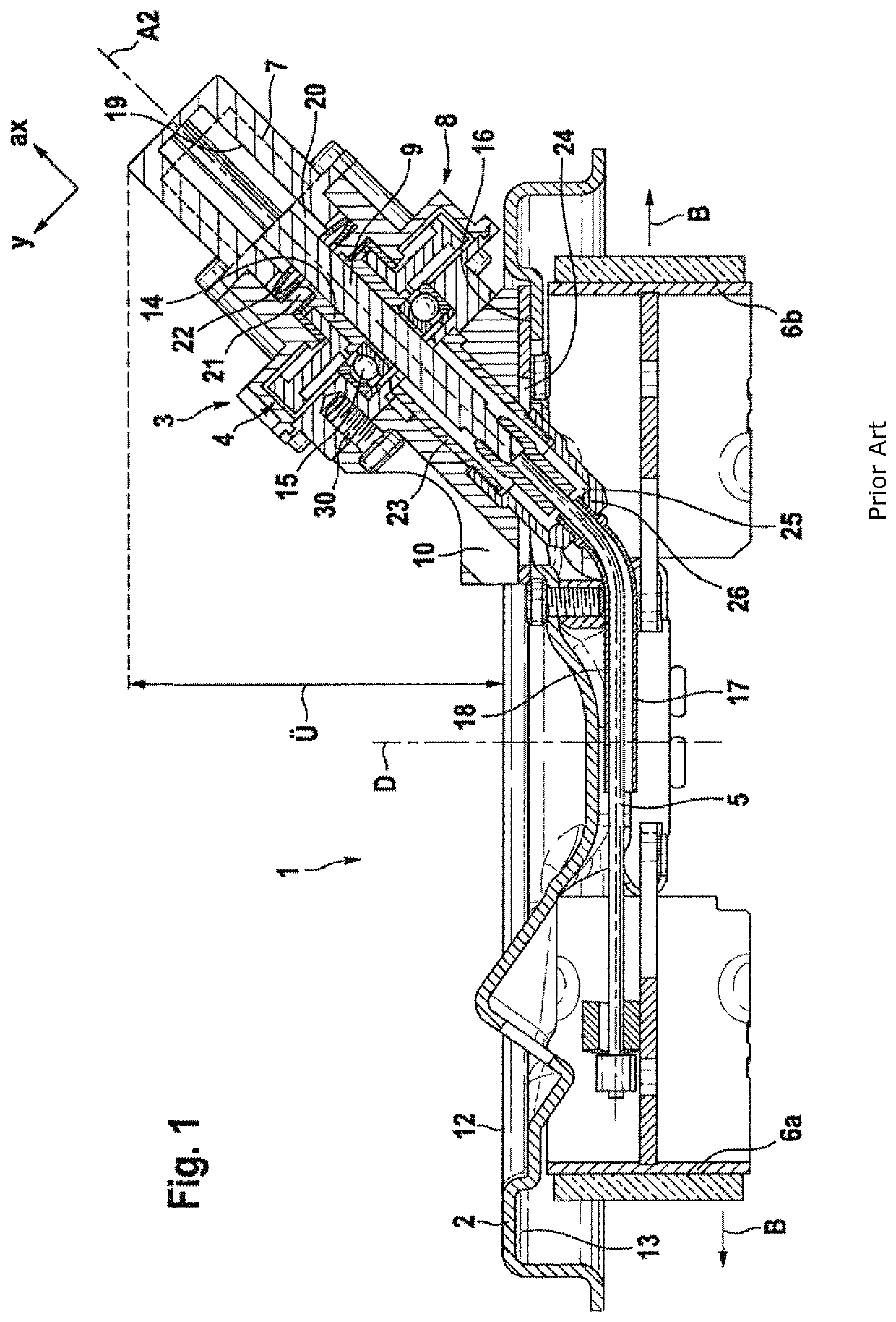
[0029]A known drum brake module 1, which can be actuated by electric motor, for arrangement on axle components of a motor vehicle comprises, as per FIG. 1, an anchor plate 2 with brake shoes 6a,b mounted thereon, which brake shoes are provided within a brake drum (not shown) on an inner side 13. On an opposite side (outer side 12) of the anchor plate 2, there is fastened a parking brake actuator 3 which is driven by electric motor and which, via a gearing 4 and a downstream actuation cable 5, engages on one or more brake shoes 6a,b such that said brake shoe(s) 6a,b can perform an actuation movement B in the direction of the brake drum in order to perform a service and / or parking brake function. The gearing 4 comprises a gearing housing 8 which receives or bears the motor 7 (concealed in the drawing by the spindle arrangement 9). The motor 7 consumes direct-current voltage, is mechanically or electronically commutated, and is of an inexpensively available standard type.

[0030]FIG. 1 s...


PUM


Abstract

A novel, particularly rationally designed, modular parking brake actuator for an electric drum brake system. An axle A1 from the motor, including a screw gear pinion coupled in a rotationally fixed manner, and an axle of the spindle arrangement, including a screw gear which is coupled in a rotationally fixed manner to the drive nut, define under a deflection of 90° a single wheel gearbox stage of the parking brake actuator.

Description

CROSS REFERENCE TO RELATED APPLICATIONS[0001]This application is the U.S. National Phase Application of PCT International Application No. PCT / EP2016 / 079726, filed Dec. 5, 2016, which claims priority to German Patent Application No. 10 2015 224 761.9, filed Dec. 10, 2015, and German Patent Application No. 10 2016 209 783.0, filed Jun. 3, 2016, the contents of such applications being incorporated by reference herein.FIELD OF THE INVENTION[0002]The present invention relates to a drum brake system with electric parking brake actuator for a motor vehicle, wherein the parking brake actuator is arranged on an outer side of an anchor plate and, in a state of rotational drive, drives a drive nut which is supported rotatably and axially fixedly on the anchor plate, which drive nut drives a spindle, which is mounted in a rotationally secured and axially displaceable manner in a gearing housing and which engages by means of an actuation cable on at least one brake shoe such that the latter can ...

Claims


Application Information

Patent Timeline
Patent Type & Authority Patents(United States)
IPC IPC(8): F16D65/22B60T13/74F16D65/18F16D51/28F16D65/00F16H25/20F16D51/00F16D51/22F16D51/24F16D55/225F16D121/04F16D121/14F16D121/16F16D121/24F16D121/26F16D123/00F16D125/40F16D125/60F16D127/02F16D129/04F16D129/10
CPCF16D65/18F16H25/20B60T13/741F16D65/00F16D51/28F16D65/22F16D2125/40F16D2121/24F16D2127/02F16D55/225F16D2121/14F16D2129/10F16D2051/006F16D2123/00F16D2121/16F16D2121/04F16D2125/60F16H2025/209F16D2129/04F16H2025/2084F16D51/22F16D51/24F16D2121/26B60T17/18F16H57/039B60Y2400/81
Inventor WINKLER, THOMASBALZ, JÜRGENFROSCHAUER, MARCOBAUER, JÜRGENWALTER, PATRICKHEINZ, STEFANMERKEL, PHILIPPBIJANZADEH, PEJMAN
Owner CONTINENTAL TEVES AG & CO OHG
Why Eureka
Try Eureka