Camera module, electronic device including the same, and method for positioning lenses of camera module

A camera and camera lens technology, applied in the camera body, TV, camera and other directions, can solve the problems of large thrust and large spring deformation, and achieve the effect of high-precision positioning

Active Publication Date: 2013-11-06
SHARP KK
View PDF2 Cites 0 Cited by
  • Summary
  • Abstract
  • Description
  • Claims
  • Application Information

AI Technical Summary

Problems solved by technology

As a result, there are problems in that a large thrust is required, and since the amount of deformation of the spring becomes large, a large strain is imparted to the spring, etc.

Method used


Image

  • Camera module, electronic device including the same, and method for positioning lenses of camera module
  • Camera module, electronic device including the same, and method for positioning lenses of camera module
  • Camera module, electronic device including the same, and method for positioning lenses of camera module

Examples


Embodiment Construction

[0082] Below, based on Figure 1 to Figure 14 , Figure 16 ~ Figure 20 Embodiments of the present invention will be described.

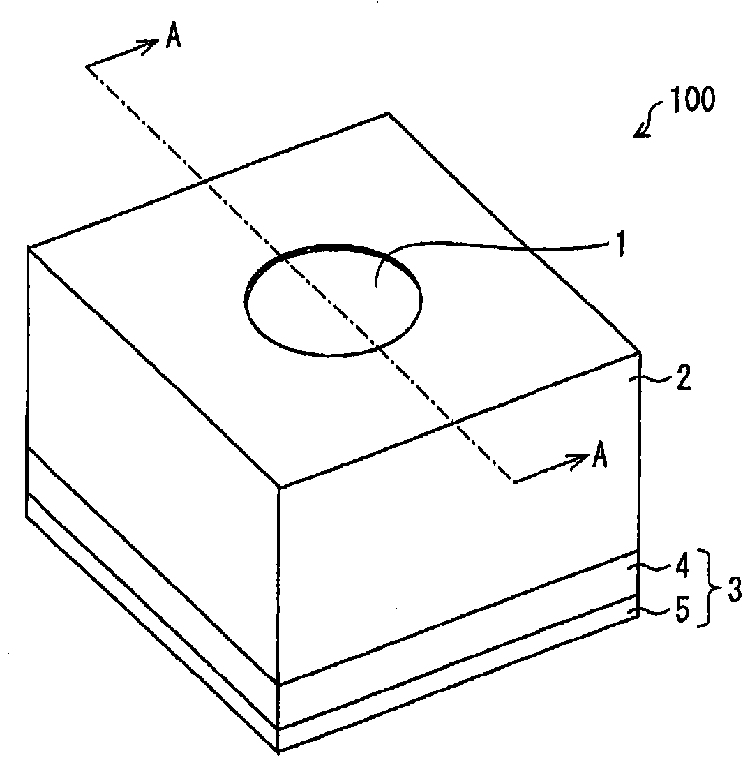
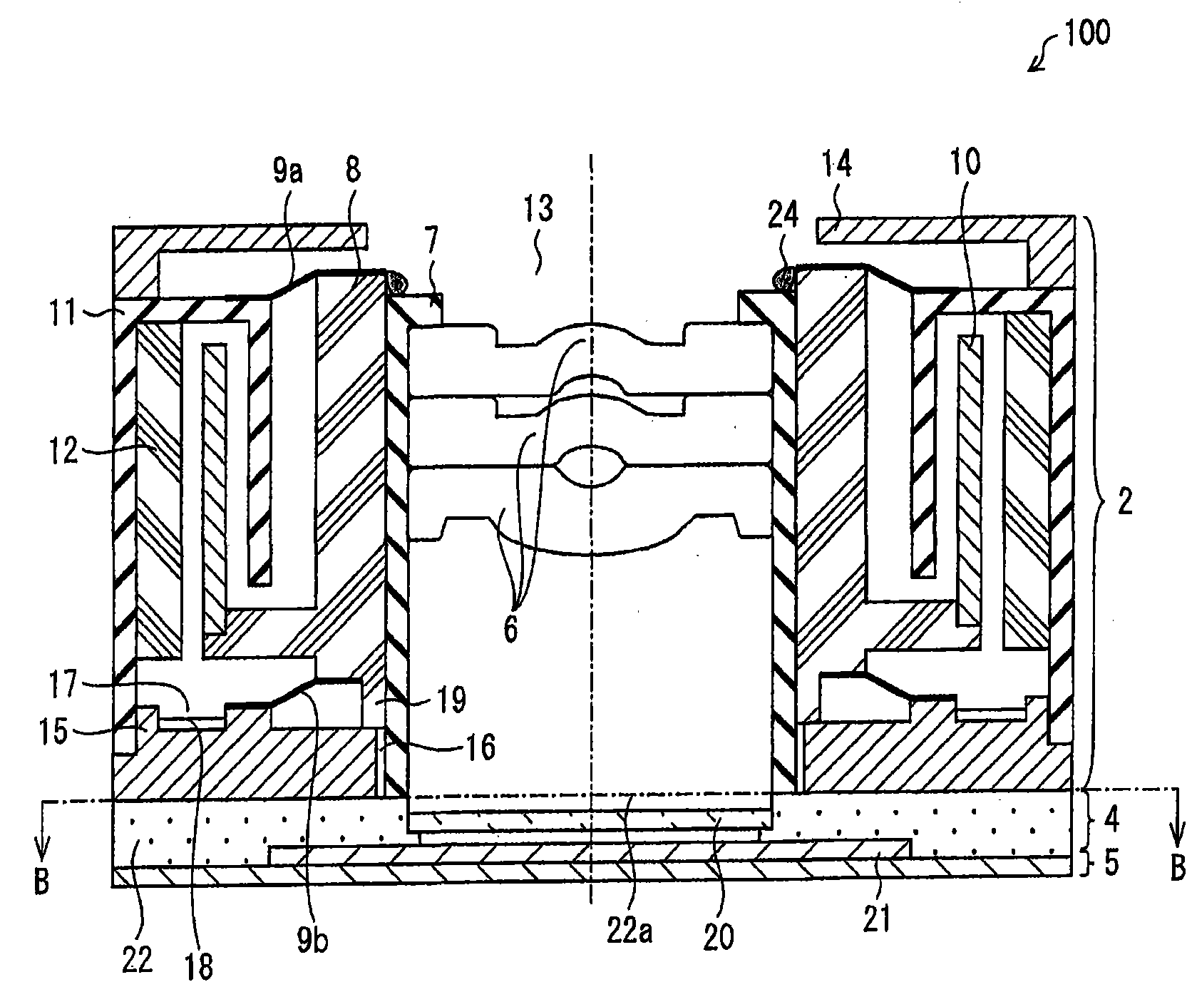
[0083] figure 1 It is a perspective view of the camera module of this embodiment. The camera module 100 includes: an optical unit 1 as an imaging optical system; a lens driving device (lens driving unit) 2 that drives the optical unit 1 ; and an imaging unit 3 that photoelectrically converts light passing through the optical unit 1 . The optical unit 1 is held inside the lens driving device 2 . The imaging unit 3 is configured to include a sensor unit 4 and a substrate 5 on which the sensor unit 4 is mounted. The camera module 100 is configured by laminating the sensor unit 4 and the lens driving device 2 sequentially in the optical axis direction on the substrate 5 . In the following description, for convenience, the side of the optical unit 1 is referred to as the upper side, and the side of the imaging unit 3 is referred to as the lower side...


PUM


Abstract

In a camera module, the position of image pickup lenses at an end at infinity is defined by contact between a bottom surface of a lens barrel and a surface of a sensor cover. This makes it possible to realize a camera module having image pickup lenses positioned with a high degree of accuracy.

Description

technical field [0001] The present invention relates to a camera module mounted in electronic equipment such as a mobile phone, and a method for positioning a camera module lens, and particularly relates to a camera module structure and method that do not require position adjustment by screws when mounting an imaging lens to a lens drive unit. The positioning method of the lens. Background technique [0002] In recent years, there have been more and more examples of mounting a camera module that uses a lens driving device to perform an autofocus function in electronic equipment such as a mobile phone. There are various types of lens driving devices such as a type using a stepping motor, a type using a piezoelectric element, and a VCM (Voice Coil Motor: Voice Coil Motor) type, and they are already in circulation in the market. [0003] When the lens is fixed to such a lens driving device, if the initial position of the lens in the optical axis direction with respect to the i...

Claims


Application Information

Patent Timeline
Patent Type & Authority Patents(China)
IPC IPC(8): G02B7/04G02B7/09H04N5/225G02B7/02G03B17/02H04N5/335
CPCH04N5/2254G02B7/023
Inventor 关本芳宏石末义人海冈真司
Owner SHARP KK
Why Eureka
Try Eureka