Supercharge Your Innovation With Domain-Expert AI Agents!

Electromagnetic signal detection circuit and detection method

A technology of electromagnetic signals and detection circuits, which is applied to electrical components, transmission monitoring, transmission systems, etc.

Inactive Publication Date: 2018-10-23
庄晴光
View PDF3 Cites 0 Cited by
  • Summary
  • Abstract
  • Description
  • Claims
  • Application Information

AI Technical Summary

Problems solved by technology

[0007] The purpose of the present invention is to provide a new electromagnetic signal detection circuit and detection method, the technical problem to be solved is to make it effectively suppress noise when the electromagnetic signal frequency becomes higher or lower

Method used


Image

  • Electromagnetic signal detection circuit and detection method
  • Electromagnetic signal detection circuit and detection method
  • Electromagnetic signal detection circuit and detection method

Examples


Embodiment Construction

[0052] A detailed description of the present invention will be discussed by means of the following examples, which are not intended to limit the scope of the present invention, but may be applicable in other applications. The illustrations reveal some details, it being understood that the details disclosed may differ from those disclosed, except in the case of expressly limited characteristics.

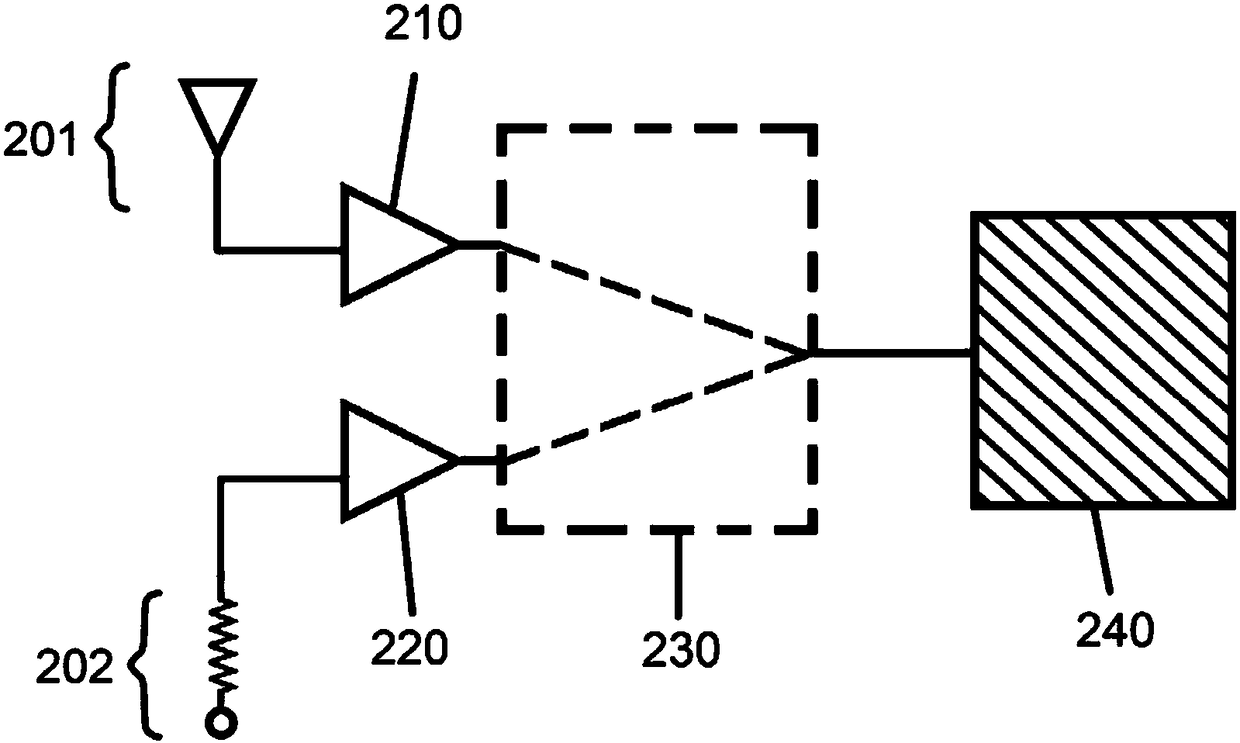
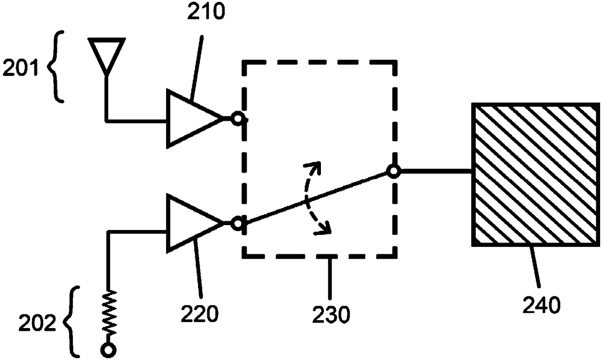
[0053] The first of the two basic structures of the electromagnetic signal detection circuit proposed by the present invention is as follows: Figure 2A shown. The first amplifier 210 and the second amplifier 220 are respectively electrically connected to both the signal source 201 for providing electromagnetic signals and the reference source 202 for providing reference signals. On the one hand, the switch 230 fixedly connects the first amplifier 210 and the second amplifier 210. The two amplifiers 220 are electrically connected to the processing circuit 240 and on the other hand re...


PUM


Abstract

The invention discloses an electromagnetic signal detection circuit and detection method. An electromagnetic signal from a signal source and a reference signal from a reference source are simultaneously amplified and alternatively transmitted to a processing circuit to perform comparison processing, or successively amplified and then alternatively transmitted to the processing circuit to perform comparison processing. Since a switcher in the prior art always has non-zero switching loss, and the gain of the amplifier can be lowered along the increasing and / or reducing of the frequency after thefrequency of the signal to be amplified exceeds the specific frequency range of the amplifier. Therefore, the electromagnetic signal can be effectively detected no matter what the switching loss of the used amplifier and / or the frequency of the received signal is.

Description

technical field [0001] The present invention relates to an electromagnetic signal detection circuit and a detection method, in particular to a switch suitable for applications where the switcher loss cannot be ignored or the frequency of the electromagnetic signal is so high or low that the gain of the amplifier is low An electromagnetic signal detection circuit and a detection method of the state. Background technique [0002] Dicke Switcher is currently commonly used to eliminate (at least reduce) the influence caused by the change of the environment where the electromagnetic signal is located or the noise of the circuit used to receive and measure the electromagnetic signal in the process of receiving and measuring the electromagnetic signal. Technology. Such as figure 1 As shown, the basic structure of the Dick switch is to use a switcher (switcher) 110 to switch between the source 101 of the electromagnetic signal to be processed and the source 102 of the reference si...

Claims


Application Information

Patent Timeline
IPC IPC(8): H04B1/04H04B1/10
CPCH04B1/0475H04B1/1027H04B17/00H04B1/04H04B1/10
Inventor 庄晴光
Owner 庄晴光
Features
  • R&D
  • Intellectual Property
  • Life Sciences
  • Materials
  • Tech Scout
  • Unparalleled Data Quality
  • Higher Quality Content
  • 60% Fewer Hallucinations
Learn More