secondary battery

A secondary battery and electrode technology, applied in secondary battery manufacturing, battery pack parts, electrolyte storage battery manufacturing, etc., can solve the problems of narrowing of the tab portion, adverse effects of subsequent processes, and large sagging of the tab portion, etc. The effect of suppressing sagging

Active Publication Date: 2021-07-20
日本汽车能源株式会社
View PDF6 Cites 0 Cited by
  • Summary
  • Abstract
  • Description
  • Claims
  • Application Information

AI Technical Summary

Problems solved by technology

Therefore, when the electrode is transported during processing and winding, the tab part interferes with the equipment, and the tab part will be cut or broken, which will adversely affect the subsequent process.
[0005] In addition, in the case of foils with different crystal states on the front and back, such as electrolytic copper foil, the sagging of the tab portion becomes larger due to internal stress.
If an electrode made of such a foil is wound, the tab part after winding will be narrowed or opened, and problems such as tab part entanglement will occur during current collection.

Method used


Image

  • secondary battery
  • secondary battery
  • secondary battery

Examples


no. 1 Embodiment approach >

[0035] Hereinafter, regarding the secondary battery of the present invention, as a first embodiment, an attached Figure 1 The cylindrical lithium ion secondary battery will be described starting from the beginning.

[0036] [Structure of Cylindrical Li-ion Secondary Battery]

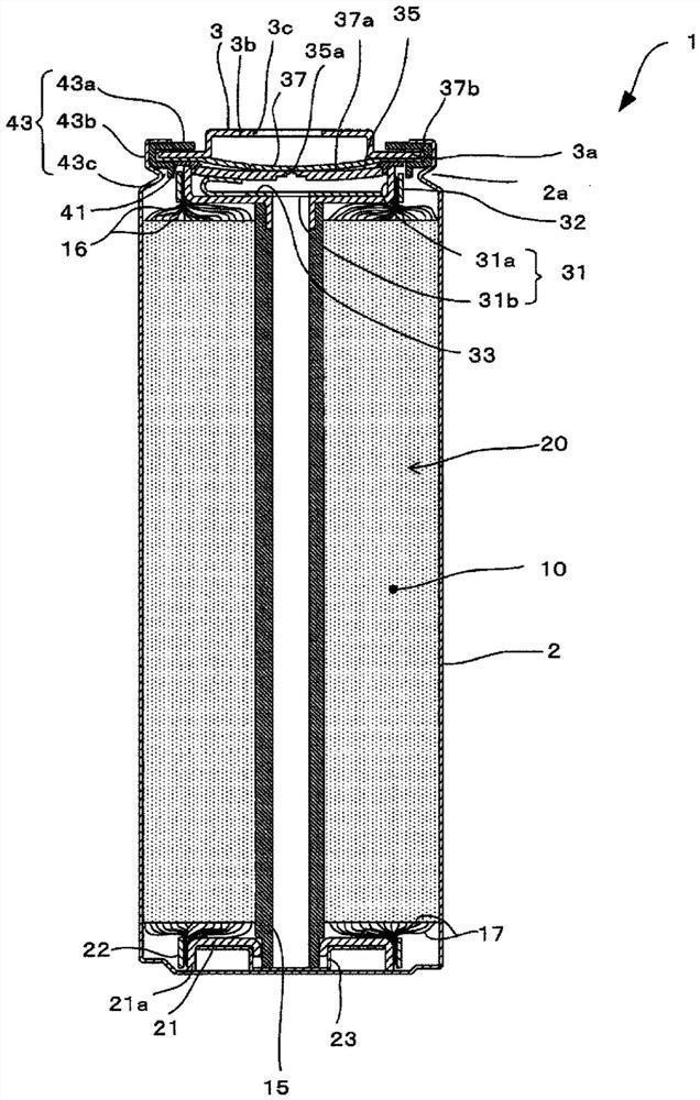
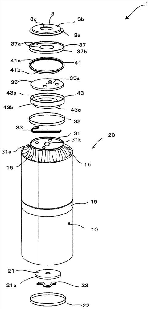
[0037] figure 1 To show a cross-sectional view of one embodiment of a cylindrical lithium ion secondary battery, figure 2 for figure 1 An exploded perspective view of the cylindrical lithium-ion secondary battery shown. The cylindrical lithium ion secondary battery 1 has, for example, an outer shape The size of height 92mm. In this cylindrical lithium ion secondary battery 1 , components for power generation described below are accommodated in a bottomed cylindrical battery can 2 and a hat-shaped upper cover 3 . In the bottomed cylindrical battery can 2, a groove 2a protruding inwardly of the battery can 2 is formed on the upper end side which is the open side.

[0038] (electrode set)

[0039...

no. 2 Embodiment approach >

[0091] Figure 12 (A) and (B) are diagrams showing the second embodiment of the deformation enhancing portion. Figure 12 (A) in (A) is the enlarged plan view near the tab, Figure 12 (B) in Figure 12 Side view of (A) in. Structure of Cylindrical Lithium Ion Secondary Battery, Manufacturing Method and Reference of Cylindrical Lithium Ion Secondary Battery Figure 1 to Figure 8 The same applies to the first embodiment described below.

[0092] Such as Figure 12 As shown in (A), for the negative electrode tab 17 and the negative electrode mixture layer uncoated region 12c integrally, one side edge 61 along the length direction of the negative electrode metal foil 12a is arranged at a predetermined interval.

[0093] Such as Figure 12 (A) in Figure 12 As shown in (B) in (B), the deformation enhancing portion is provided at the position of the uncoated region 12 c of the negative electrode mixture layer corresponding to the position of the negative electrode tab 17 . T...

no. 3 Embodiment approach >

[0096] Figure 13 (A) and (B) are diagrams showing the third embodiment of the deformation enhancing portion. Figure 13 (A) in (A) is the enlarged plan view near the tab, Figure 13 (B) in Figure 13 Side view of (A) in. Structure of Cylindrical Lithium Ion Secondary Battery, Manufacturing Method and Reference of Cylindrical Lithium Ion Secondary Battery Figure 1 to Figure 8 The same applies to the first embodiment described.

[0097] Such as Figure 13 As shown in (A), the negative electrode tabs 17 are integrally arranged at predetermined intervals along one side edge 61 of the negative electrode metal foil 12a in the longitudinal direction with the uncoated region 12c of the negative electrode mixture layer.

[0098] Such as Figure 13 (A) in Figure 13 As shown in (B), the deformation enhancing part is provided at the position of the negative electrode mixture layer uncoated region 12 c corresponding to the position of the negative electrode tab 17 and the central...


PUM

PropertyMeasurementUnit
heightaaaaaaaaaa
thicknessaaaaaaaaaa
thicknessaaaaaaaaaa

Abstract

There are disadvantages in that the uncoated region of the mixture layer, which is the base of the tab portion, has a large amount of sag, and the effect of suppressing the amount of sag as a whole of the tab portion is small. Negative electrode tabs (17) are arranged on the negative electrode of the negative electrode (12) integrally with the uncoated region (12c) of the negative electrode mixture layer along the side edge (61) of the length direction of the negative electrode metal foil (12a) at predetermined intervals. metal foil (12a). The mixture layer uncoated region (12c) has a concave fold portion (50) (deformation enhanced portion) in which a concave portion is formed. By setting the negative electrode mixture layer uncoated region (12)c into a shape with a concave fold (50), its rigidity and the planar shape without the concave fold (50) become larger, and the negative electrode due to gravity, etc. The sagging angle of the uncoated area (12c) of the mixture layer becomes smaller, so the sagging amount of the negative electrode tab (17) connected to the uncoated area (12c) of the negative electrode mixture layer can be reduced.

Description

technical field [0001] The present disclosure relates to secondary batteries Background technique [0002] In a secondary battery such as a lithium ion secondary battery, a positive electrode having a positive electrode mixture layer and a negative electrode having a negative electrode mixture layer are wound around a shaft core via a separator to form an electrode group. The positive electrode mixture layer is formed on both sides of the positive electrode sheet, and one side edge of the positive electrode sheet along the longitudinal direction is set as the positive electrode mixture layer uncoated area where the positive electrode mixture layer is not formed. For the non-coated area of ​​the positive electrode mixture layer, in order to weld the positive electrode to the positive electrode current collecting member, generally, a plurality of positive electrode leads (positive electrode tabs) called tabs are arranged at a predetermined length on one edge of the positive el...

Claims


Application Information

Patent Timeline
Patent Type & Authority Patents(China)
IPC IPC(8): H01M10/04H01G11/26H01G11/70H01G11/74H01M4/70H01M4/78H01M10/058H01M50/528H01M50/531H01M4/02H01M50/534H01M50/536
CPCH01G11/26H01G11/70H01G11/74H01M4/70H01M4/78H01M10/058Y02E60/10Y02P70/50H01M50/534H01M50/536
Inventor 八木阳心森川拓是内藤匡
Owner 日本汽车能源株式会社
Why Eureka
Try Eureka