Connector

A connector and contact technology, which is applied in the direction of connection, parts and electrical components of the connecting device, etc., can solve the problems of disordered high-frequency characteristics of the connector, and achieve the effects of easy impedance matching, suppression of changes, and stable maintenance.

Active Publication Date: 2018-10-23
HIROSE ELECTRIC GROUP
View PDF6 Cites 2 Cited by
  • Summary
  • Abstract
  • Description
  • Claims
  • Application Information

AI Technical Summary

Problems solved by technology

Therefore, among the plurality of terminals held by the housing, the portion exposed from the hole to the outside is easily affected from the outside. As described above, similar to the m

Method used


Image

  • Connector
  • Connector
  • Connector

Examples


Example Embodiment

[0067] Embodiments of the present invention will be described below with reference to the accompanying drawings. In addition, in all the drawings for explaining the embodiment, the same components are given the same reference numerals as a principle, and their overlapping descriptions are omitted. In addition, although each embodiment is demonstrated independently, it does not exclude the case where a connector is comprised by combining mutual components.

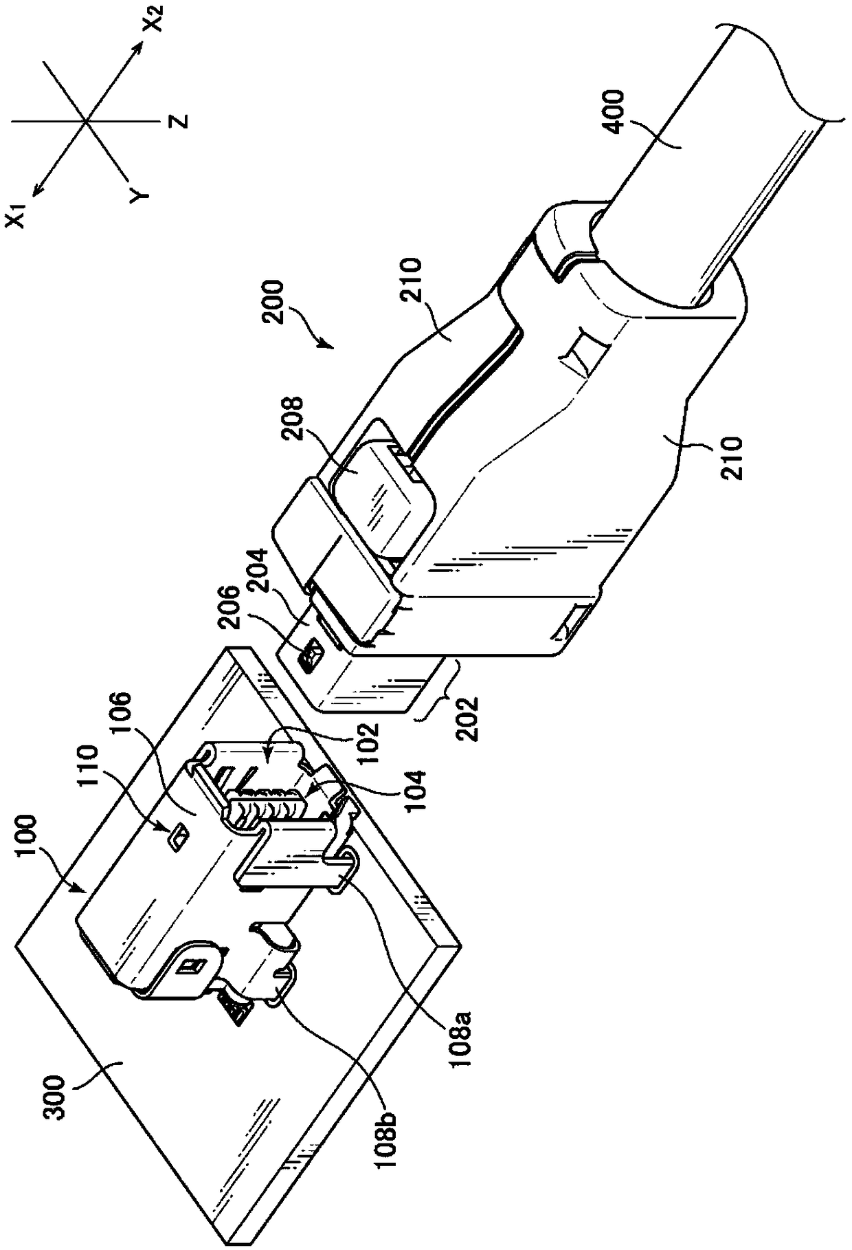
[0068] figure 1 It is a diagram showing the appearance of the connector on the board side and the connector on the cable side. The mating direction of the connector is the X1-X2 direction (X-axis direction) in the figure. The front end side of the connector 100 on the board side is the X2 direction side, and the front end side of the cable side connector 200 is the X1 direction side. The plane perpendicular to the substrate 300 is the X-Z plane, and the plane (parallel plane) horizontal to the substrate 300 is the X-Y pl...


PUM


Abstract

The invention provides a connector. When a housing is to be integrally molded so as to hold a plurality of terminals therein, there is a jig for fixing the plurality of terminals in a fixed position inside a metal mold, and therefore, a material such as synthetic resin hardens around said jig, and after the jig has been removed from the plurality of terminals, a hole is formed by the jig on the outer surface of the housing, the portion exposed to the exterior from said hole is susceptible to external effects, and a technical problem can arise in which the high-frequency characteristics of theconnector are readily disturbed. To address this problem, provided is a connector in which the housing is divided into a first housing member (150a) for holding a first terminal group, and a second housing member (150b) for holding a second terminal group, and a plurality of holes (168, 170), which are generated by the jig respectively supporting a plurality of terminals included in the terminal group, are provided where the surfaces (180, 182) of the first and second housing members meet, whereby external effects on high-frequency characteristics can be reduced without holes in the outer surface of the configured housing.

Description

technical field [0001] The present invention relates to a connector suitable for high-speed transmission of electrical signals. Specifically, it relates to a structure in which an insulating housing that fixes a plurality of terminals included in a connector can be arranged so as to maintain impedance matching. Background technique [0002] A connector used for transmitting electrical signals generally includes an insulating housing that holds one terminal group to face the other terminal group, and an outer conductor case that accommodates the housing. For example, the connector described in Japanese Patent No. 2011-233337 (Patent Document 1) includes: a plurality of terminals arranged at intervals from each other, and one terminal group arranged in the upper part, and the other terminal group arranged in the lower part. A plurality of terminals arranged in a facing manner; a terminal holding member (housing) for maintaining the insulation of each terminal; The plurality ...

Claims


Application Information

Patent Timeline
IPC IPC(8): H01R13/6474H01R13/502H01R13/6581
CPCH01R13/502H01R13/6474H01R13/6581
Inventor 境泽直志长沼健一
Owner HIROSE ELECTRIC GROUP
Why Eureka
Try Eureka