Discharge tube

A discharge tube and discharge active technology, which is applied in the field of discharge tubes, can solve the problems of large distance between the discharge trigger film and the coating film, the change of working voltage, and the deviation of working voltage, so as to reduce the scattering of the discharge active layer, stabilize the working voltage, and suppress the change Effect

Active Publication Date: 2018-04-20
MITSUBISHI MATERIALS CORP
View PDF6 Cites 1 Cited by
  • Summary
  • Abstract
  • Description
  • Claims
  • Application Information

AI Technical Summary

Problems solved by technology

[0009] That is, in the above-mentioned prior art, the discharge activating material coating for assisting discharge is formed on the central portion of the front end surface of the discharge electrode, but in this case, the discharge triggering film formed on the inner surface of the insulating hollow body and the coating The distance is relatively large, and the working voltage is unstable.
In particular, the arc discharge transferred from the glow discharge at the initial stage of the discharge is mostly generated in the central part of the discharge electrode, and the discharge active layer in the central part of the discharge electrode is scattered by the arc discharge and adhered to the surroundings, thereby appearing the operating volta

Method used


Image

  • Discharge tube
  • Discharge tube
  • Discharge tube

Examples


Example Embodiment

[0057] Example

[0058] Next, regarding the embodiments of the present invention, refer to Figure 6 to Figure 8 The electrical characteristics (discharge characteristics) of the gas arrester (discharge tube) in which the discharge active layer is formed on the surface of the sealing electrode will be described.
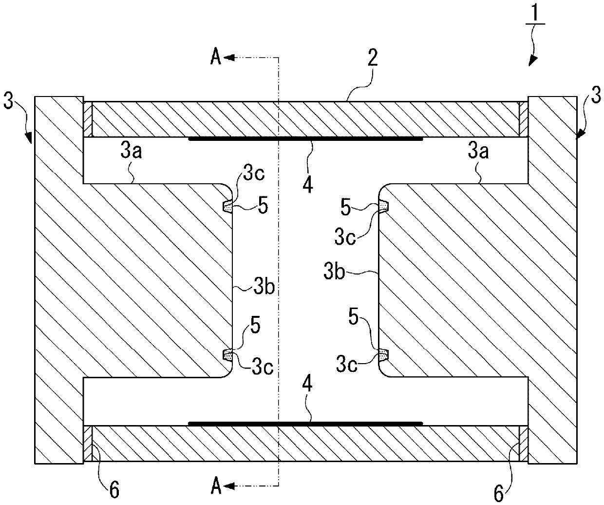
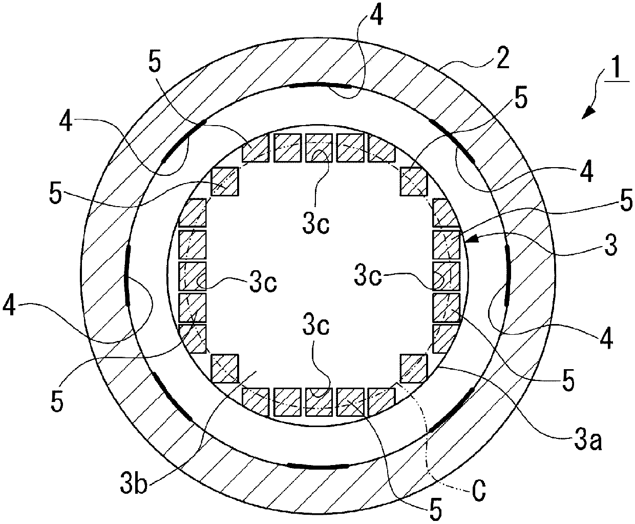
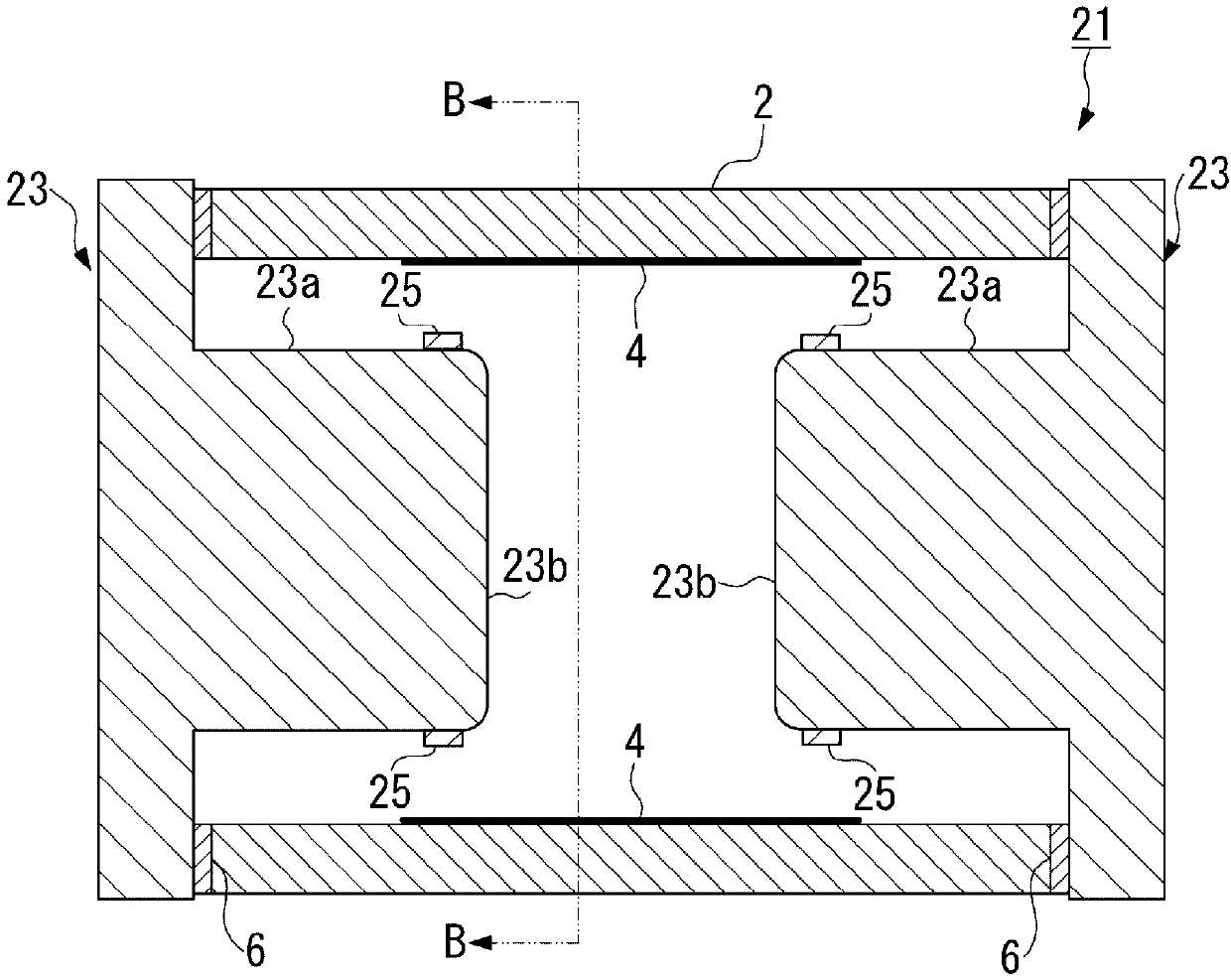
[0059] As an example of the present invention, the discharge tube described in the above-mentioned first embodiment was produced as Example 1, and the discharge tube described in the above-mentioned second embodiment was produced as Example 2.

[0060] In addition, in the preparation of samples for evaluating electrical characteristics, insulating hollow bodies and sealing electrodes of the same size were used, and the discharge control gas, pressure, and gas sealing procedures filled in the gas arrester were also the same. Furthermore, the discharge start voltage of each sample was set to be the same 350V, and factors other than the formation position of the discharge act...


PUM


Abstract

The invention discloses a discharge tube which can improve the stability of an operational voltage in repeated discharges. The present invention is provided with: a cylindrical insulating hollow body2 that has openings in at least both ends thereof; and at least a pair of sealing electrodes 3 that face each other and seal a discharge control gas inside the insulating hollow body by closing the openings thereof. A discharge trigger film 4, which is formed of a conductive material, is provided on an inner circumferential surface of the insulating hollow body. The sealing electrodes each includea protruding part 3a that protrudes toward the inside of the insulating hollow body and a discharge active layer 5 that is formed at a leading end portion of the protruding part and is formed of a material having a higher electron discharge property than the material of the sealing electrodes. The discharge active layer is formed in a plurality or in an extended manner at the leading end portionof the protruding part and in the vicinity of an outer circumferential edge of a leading end surface of the protruding part, along the outer circumferential edge. A center portion of the leading end surface constitutes a region in which the discharge active layer is not formed.

Description

technical field [0001] The present invention relates to a discharge tube used as a surge absorber or a switching discharger (Switching sparkgap) for spark plug lighting, which is used to protect various equipment from surges (Surge) generated by lightning, etc., to prevent accidents. Before it happens. Background technique [0002] Discharge tubes are also used, for example, in gas arresters (gas arresters), high-pressure discharge lamps, and switching arresters for spark plugs, which are used to prevent malfunctions of electronic equipment due to overvoltages such as lightning strikes and static electricity. [0003] The stability of the operating voltage during repeated discharges, excellent withstand voltage characteristics, and the like are required for discharge tubes as such lightning strike countermeasures and switching arresters. In order to obtain such repeated operation stability, excellent withstand voltage characteristics, etc., a technique of forming a discharg...

Claims


Application Information

Patent Timeline
IPC IPC(8): H01T4/12H01T1/20H01T2/02
CPCH01T1/20H01T1/22H01T2/02H01T4/12
Inventor 酒井信智黛良享杉本良市
Owner MITSUBISHI MATERIALS CORP
Why Eureka
Try Eureka