Oil cylinder slider front-mold firstly-core-pulling injection molding mold

A technology of injection mold and oil cylinder, which is applied in the field of injection mold mechanism design, can solve the problems of high mold manufacturing cost and complex mold structure, and achieve the effect of reducing structural difficulty and manufacturing cost, reducing structural difficulty and manufacturing difficulty, and large core pulling

Inactive Publication Date: 2018-10-26
乌鲁木齐九品芝麻信息科技有限公司
View PDF0 Cites 6 Cited by
  • Summary
  • Abstract
  • Description
  • Claims
  • Application Information

AI Technical Summary

Problems solved by technology

[0002] When the product has an oblique demoulding feature on the front mold side, it is necessary to set the surface mold first core-pulling mechanism on the front mold for demoulding. Generally, the demoulding power of the front mold first core-pulling mechanism comes from the opening and closing power of the mold template , through the opening and closing power of the template of the mold to drive the bent pin or the inclined guide column to drive the slider to pull the core, but these are only suitable for small oblique holes with tight wrapping force, but not suitable for the situation with large wrapping force. And the mold structure is complex, and the manufacturing cost of the mold is high

Method used


Image

  • Oil cylinder slider front-mold firstly-core-pulling injection molding mold
  • Oil cylinder slider front-mold firstly-core-pulling injection molding mold
  • Oil cylinder slider front-mold firstly-core-pulling injection molding mold

Examples


Embodiment Construction

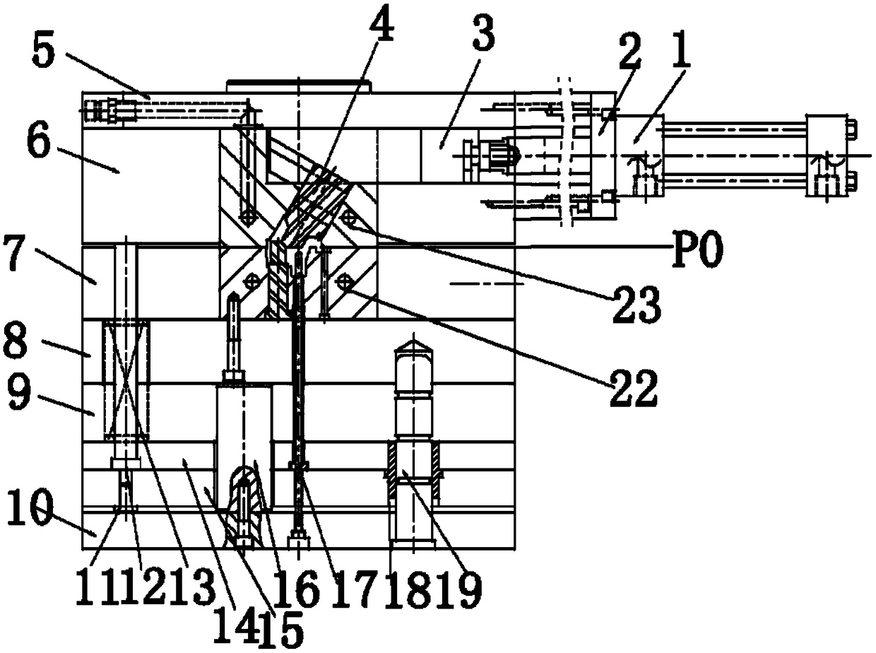
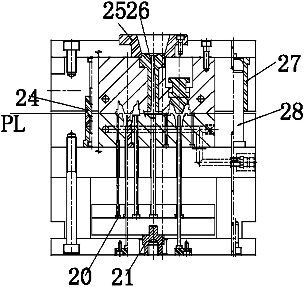
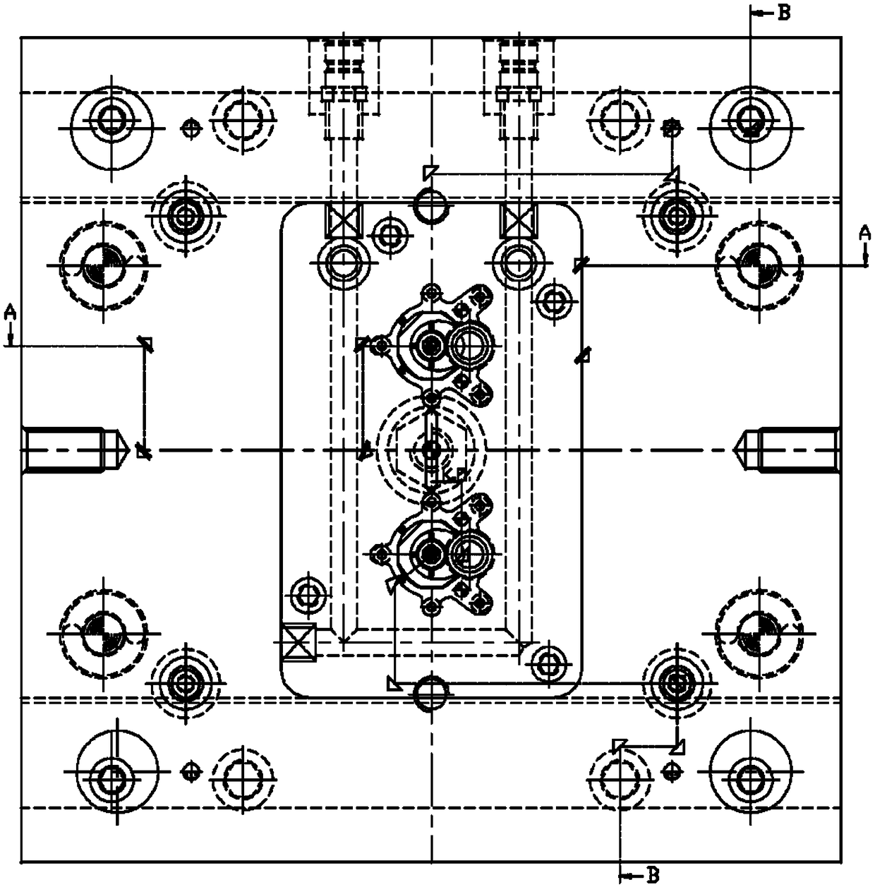
[0018] Figure 1-4 Shown is the relevant explanatory figure of the present invention; The specific embodiment is, as figure 1 , figure 2 , image 3 , Figure 4 As shown, a core-pulling injection mold for the front mold of the cylinder row position includes a core-pulling drive cylinder 1 for the front mold, a sliding support for the oil cylinder 2, a horizontal core-pulling slider body 3, an oblique core-pulling insert 4, a panel 5, a fixed Template 6, movable template 8, movable mold pad 9, movable mold bottom plate 10, garbage nail 11, reset lever 12, reset lever spring 13, thimble panel 14, thimble push plate 15, support column 16, push tube 17, thimble plate Guide sleeve 18, thimble plate guide post 19, thimble pin 20, ejector rod sleeve 21, male mold insert 22, female mold insert 23, positioning taper sleeve 24, positioning ring 25, sprue bushing 26, fixed mold guide sleeve 27 , fixed mold guide post 28.

[0019] The oblique core-pulling assembly driven by the front...


PUM


Abstract

The invention provides an oil cylinder slider front-mold firstly-core-pulling injection molding mold. The mold structurally comprises a front-mold oil cylinder driven inclined-core-pulling assembly, amold base structure assembly, a jacking-out mechanism assembly, a mold cavity forming assembly, a pouring system assisting assembly and a mold positioning mechanism assembly. A two-plate-mold cold runner side gate pouring mode is adopted for the structural layout of the mold, and the mold layout is of a one-mold two-cavity mode. A pipe water cooling mode is adopted for cooling, an exhaust edge exhaust manner is adopted for exhaust, and the exhaust gap is 0.02 mm. The technical problem that a product front mold requires core pulling and demoulding and is large in packaging force, a core pulling mechanism cannot perform core pulling and demoulding easily and reliably when a general inclined guide pillar or a bent pin is used for core pulling, the manufacturing cost of the mold is high, theoccupied mold structure space is large, and arrangement of other auxiliary mechanisms of the mold is not facilitated are solved. The oil cylinder slider front-mold firstly-core-pulling injection molding mold has the beneficial effects that straightly driven type core pulling and demoulding are performed through an oil cylinder plus an inclined slider, the reliability of the action of a core pulling and demoulding mechanism is improved, the structure difficulty of the mold is lowered, the manufacturing cost of the mold is lowered, and the mold structure space is effectively utilized.

Description

technical field [0001] The invention relates to the field of mechanism design of an injection mold, in particular to an injection mold with a core-pulling before the cylinder row position. Background technique [0002] When the product has an oblique demoulding feature on the front mold side, it is necessary to set the surface mold first core-pulling mechanism on the front mold for demoulding. Generally, the demoulding power of the front mold first core-pulling mechanism comes from the opening and closing power of the mold template , through the opening and closing power of the template of the mold to drive the bent pin or the inclined guide column to drive the slider to pull the core, but these are only suitable for small oblique holes with tight wrapping force, but not suitable for the situation with large wrapping force. Moreover, the structure of the mold is complicated, and the manufacturing cost of the mold is high. Contents of the invention [0003] The technical p...

Claims


Application Information

Patent Timeline
Patent Type & Authority Applications(China)
IPC IPC(8): B29C45/33B29C45/44
CPCB29C45/332B29C45/44
Inventor 不公告发明人
Owner 乌鲁木齐九品芝麻信息科技有限公司
Why Eureka
Try Eureka