Small aircraft engine multi-point rubbing fault simulation experiment device

An aero-engine and experimental device technology, which is applied in the field of aero-engines, can solve problems such as difficult simulation, large differences in friction failures, and inability to simulate engine working conditions, etc., to achieve the effect of ensuring safety and ensuring safety

Active Publication Date: 2018-10-26
南京领航智能航空科技有限公司
View PDF6 Cites 19 Cited by
  • Summary
  • Abstract
  • Description
  • Claims
  • Application Information

AI Technical Summary

Problems solved by technology

However, the existing rubbing test bench simplifies the complex engine structure, and is mainly aimed at the research of a single rubbing problem, which is quite different from the rubbing fault in the actual operation of aero-engines.
[0004] Small aero-engine rotor systems generally use centrifugal compressors and axial-flow turbines. Both compressors and turbines are parts that work under high-speed rotation. They are affected by various loads during work, including inertial force, centrifugal force, and aerodynamic force. Complete simplification of the rotor system to a different form of disk and shaft structure does not simulate real engine operation
[0005] Small aeroengines are compact in structure. When the engine vibrates greatly due to blade damage, loose bearings, misalignment, rotor imbalance, etc., various forms of friction between the rotor and the stator may occur at multiple locations, which requires the study of engine The vibration response characteristics under the action of various friction-touch couplings, but it is difficult for the existing experimental devices to simulate this phenomenon more realistically

Method used


Image

  • Small aircraft engine multi-point rubbing fault simulation experiment device
  • Small aircraft engine multi-point rubbing fault simulation experiment device
  • Small aircraft engine multi-point rubbing fault simulation experiment device

Examples


Embodiment Construction

[0031] The present invention will be described in detail below in conjunction with the accompanying drawings and specific embodiments.

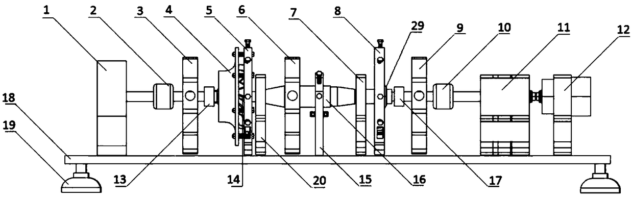
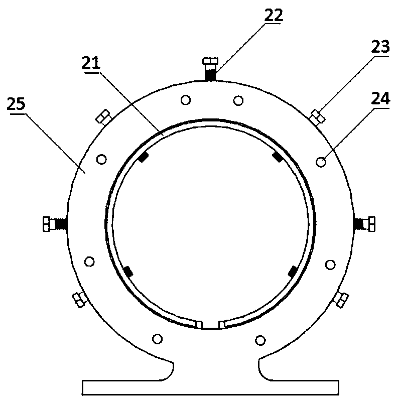
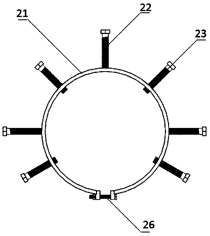
[0032] Such as figure 1 — Image 6 As shown, the small aeroengine multi-point rubbing fault simulation experiment device provided by the present invention includes a rotor system, a rubbing system, a drive system, a support system and a measurement and control system;

[0033] Wherein the supporting system comprises left bearing seat 20, right bearing seat 7, left sensor support 3, middle sensor support 6, right sensor support 9, test bench base 18 and damping support 19; described test bench base 18 is horizontally arranged , a vibration-damping support 19 is respectively installed at the four corners of the bottom surface; the left sensor bracket 3, the left bearing seat 20, the middle sensor bracket 6, the right bearing seat 7 and the right sensor bracket 9 are installed on the base of the test bench at intervals from left to right The m...


PUM


Abstract

A small aircraft engine multi-point rubbing fault simulation experiment device includes a rotor system, a drive system, a rubbing system, a support system, and a measurement and control system. The rotor system adopts a centrifugal compressor and a leaf disc integrated structure axial flow turbine, which is consistent with the real structure of the small aircraft engine; the drive system includesa motor, a speed increaser and a magnetic powder brake; the rubbing system includes a compressor rubbing structure, a turbine rubbing structure and a rotating shaft rubbing structure, wherein each structure is an independent structure, and the structures can be combined with each other to realize multi-position and multi-modal coupling rubbing; the measurement and control system includes a motor rotating speed controller, a motor comprehensive protector, a data collector, a displacement sensor and a vibration acceleration sensor, wherein the motor comprehensive protector can prevent damage tothe motor under a high load. The invention can realistically simulate multi-type rubbing faults of the small aircraft engine rotor system at multiple locations, and can be used to study the vibrationresponse of the small aircraft engine under a plurality of frictional coupling effects.

Description

technical field [0001] The invention belongs to the technical field of aeroengines, in particular to a small aeroengine rotor failure simulation experiment device. Background technique [0002] Small aeroengines have the characteristics of small size, light weight, and high thrust-to-weight ratio. In recent years, they have been widely used in small aircraft such as drones, target drones, and missiles. In order to improve the thrust and efficiency of the engine, the gap between the rotor and the stator of the engine is getting smaller and smaller. When the rotor vibrates beyond the allowable gap, the rotor and the stator will rub against each other. Since small aero-engines generally rotate at a relatively high speed, friction between the engine rotor and the stator will cause severe vibration of the whole engine, which usually leads to serious flight accidents. [0003] Common rubbing forms of aeroengine rotor and stator include single-point rubbing, multi-point rubbing, p...

Claims


Application Information

Patent Timeline
Patent Type & Authority Applications(China)
IPC IPC(8): G01M15/02
CPCG01M15/02
Inventor 张鸿李湘萍孔庆国崔东泽刑海龙
Owner 南京领航智能航空科技有限公司
Why Eureka
Try Eureka