Integrated imaging display device

A display device and integrated imaging technology, applied in the directions of instruments, electrical components, circuits, etc., can solve the problems of poor three-dimensional effect of the integrated imaging display device, and achieve the effect of improving the three-dimensional display effect and eliminating the moiré pattern.

Inactive Publication Date: 2018-10-26
BOE TECH GRP CO LTD
View PDF4 Cites 6 Cited by
  • Summary
  • Abstract
  • Description
  • Claims
  • Application Information

AI Technical Summary

Problems solved by technology

[0004] An embodiment of the present invention provides an integrated imaging display device to solve the problem in the prior art that the three-dimensional effect of the integrated imaging display device is poor due to the appearance of moiré

Method used


Image

  • Integrated imaging display device
  • Integrated imaging display device
  • Integrated imaging display device

Examples


Embodiment Construction

[0042] To solve the problem in the prior art that the three-dimensional effect of the integrated imaging display device is poor due to the appearance of moiré, an embodiment of the present invention provides an integrated imaging display device.

[0043] The specific implementation manners of the integrated imaging display device provided by the embodiments of the present invention will be described in detail below with reference to the accompanying drawings. The thickness and shape of each film layer in the drawings do not reflect the real scale, and the purpose is only to illustrate the content of the present invention.

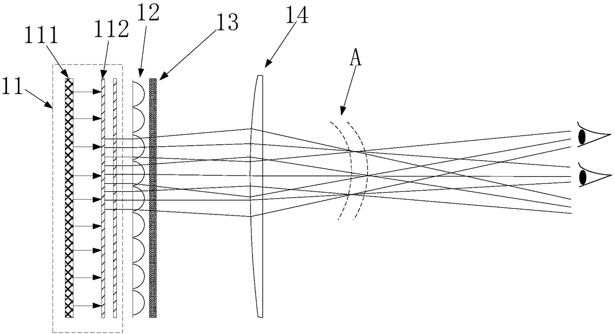
[0044] An embodiment of the present invention provides an integrated imaging display device, such as figure 2 As shown, it includes: a display device 11, and a microlens array 12 and a low-pass filter device 13 located on the light-emitting side of the display device 11; wherein,

[0045] The display device 11 includes: a plurality of display units for di...


PUM


Abstract

The invention discloses an integrated imaging display device comprising a display device and a micro-lens array and a low-pass filter device which are arranged on the light emergent side of the display device. The display device comprises multiple display units which are used for displaying different angles of three-dimensional image information. The micro-lens array is used for integrating the three-dimensional image information displayed by each display unit into a three-dimensional image. The low-pass filter device is used for filtering the Moire patterns which can be identified by the human eyes. According to the integrated imaging display device, the low-pass filter device capable of filtering the Moire patterns which can be identified by the human eyes is arranged on the light emergent side of the display device so that the Moire patterns generated by each device of the light emergent side of the low-pass filter device can be weakened or eliminated and the three-dimensional display effect of the integrated imaging display device can be enhanced.

Description

technical field [0001] The invention relates to the field of display technology, in particular to an integrated imaging display device. Background technique [0002] Because integrated imaging has many advantages such as being able to display real-time 3D images with full true color and full parallax, it has become a research hotspot in the field of naked-eye 3D display. The basic principle is to use the microlens array to record the spatial field on the film behind the microlens array, each microlens corresponds to an image element on the film, each image element records a part of the information in the space scene, and all image elements are integrated The image element array formed together records the three-dimensional information of the entire space scene. According to the principle of reversible optical path, if the same microlens array is placed in front of the image element array when recording, the original three-dimensional information can be restored in front of t...

Claims


Application Information

Patent Timeline
Patent Type & Authority Applications(China)
IPC IPC(8): G02B27/22G02B27/46
CPCG02B27/46G02B30/27H01L25/167G02B5/3083G02B27/288G02B30/10H10K59/38H10K50/858G02B3/0062G02B5/20G02B27/60G02F1/133526G02F1/13363G02F1/1347G02F2413/01G02F2413/02G02F2413/08H01L25/0657H10K59/12
Inventor 魏宝强陈小川赵文卿陈祯祐牛小辰
Owner BOE TECH GRP CO LTD
Why Eureka
Try Eureka