Displayer and display panel thereof

A display panel and display component technology, applied in the direction of instruments, optical components, optics, etc., can solve problems such as unsuitable system integration, complex multi-focus system structure, etc., to achieve the effect of improving 3D display effect, increasing depth of field, and easy integration

Active Publication Date: 2018-06-15
WUHAN CHINA STAR OPTOELECTRONICS TECH CO LTD
View PDF4 Cites 6 Cited by
  • Summary
  • Abstract
  • Description
  • Claims
  • Application Information

AI Technical Summary

Problems solved by technology

However, the existing multi-focus system structure is relatively complex, not suitable for system integration

Method used


Image

  • Displayer and display panel thereof
  • Displayer and display panel thereof
  • Displayer and display panel thereof

Examples


Embodiment Construction

[0022] Hereinafter, embodiments of the present invention will be described in detail with reference to the accompanying drawings. This invention may, however, be embodied in many different forms and should not be construed as limited to the specific embodiments set forth herein. Rather, the embodiments are provided to explain the principles of the invention and its practical application, thereby enabling others skilled in the art to understand the invention for various embodiments and with various modifications as are suited to particular intended uses. In the drawings, the same reference numerals will be used to denote the same elements throughout.

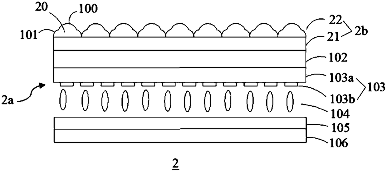
[0023] refer to figure 2 , image 3 , the display provided in this embodiment may be a liquid crystal display, or may be an OLED, and the liquid crystal display is taken as an example to describe the display in this embodiment. The display includes a backlight module 1 and a display panel 2 , and the backlight module 1 provid...


PUM


Abstract

The invention provides a displayer and a display panel thereof. The display panel comprises a display component and a micro-lens structure which is arranged on the display component. The micro-lens structure comprises a substrate and a micro-lens array. The micro-lens array is arranged on the surface, which is back to the display component, of the substrate. The micro-lens array comprises multiplemicro-lenses which are arranged in arrays. The shape of the micro-lenses is the shape formed by multiple continuous curves rotating around the axis. The shape of the micro-lenses is set as the shapeformed by multiple continuous curves rotating around the axis so that the parallel light emitted by the display component can be converged to two focal points, the depth of field of light field 3D display can be increased and the 3D display effect can be improved and the micro-lens structure is simple in structure and easy to integrate.

Description

technical field [0001] The invention relates to the technical field of displays, in particular to a display and a display panel thereof. Background technique [0002] Light field 3D display technology is a popular naked-eye 3D display technology that has emerged in recent years. It is based on the basic principle of four-dimensional light field reproduction. information; therefore, the ray information with direction must be recorded to fully restore the 3D scene. Usually, a ray is uniquely represented by recording the intersection coordinates of the spatial ray and two parallel planes, such as figure 1 As shown, A and B are two parallel planes in space, and light C intersects the two planes at A 0 (x a ,y a ), B 0 (x b ,y b ) two points, through the position of the intersection point on the two planes, the direction information of the light can be obtained, which is A 0 B 0 (x b -x a ,y b -y a ), the focus can be re-completed only by re-tracing the light rays, t...

Claims


Application Information

Patent Timeline
Patent Type & Authority Applications(China)
IPC IPC(8): G02B27/22
CPCG02B30/27
Inventor 邓泽方
Owner WUHAN CHINA STAR OPTOELECTRONICS TECH CO LTD
Why Eureka
Try Eureka