
Automatic control device for realizing circular rock joint contact state and automatic control method for realizing circular rock joint contact state

A technology of automatic control and rock jointing, applied in the direction of electrical program control, sequence/logic controller program control, etc., can solve the problems of inapplicability, limited drilling tool size, etc., and achieve the effect of preventing damage

Inactive Publication Date: 2018-10-26
CHINA UNIV OF GEOSCIENCES (WUHAN)
View PDF6 Cites 0 Cited by
  • Summary
  • Abstract
  • Description
  • Claims
  • Application Information

AI Technical Summary

Problems solved by technology

Due to the limited size of the drilling tool (the inner diameter of the commonly used drilling tool is 50mm), the method of staggering different displacements in the radial direction to obtain different contact states is not applicable

Method used


Image

  • Automatic control device for realizing circular rock joint contact state and automatic control method for realizing circular rock joint contact state

Examples


Embodiment Construction

[0019] In order to make the purpose, technical solution and advantages of the present invention clearer, the embodiments of the present invention will be further described below in conjunction with the accompanying drawings.

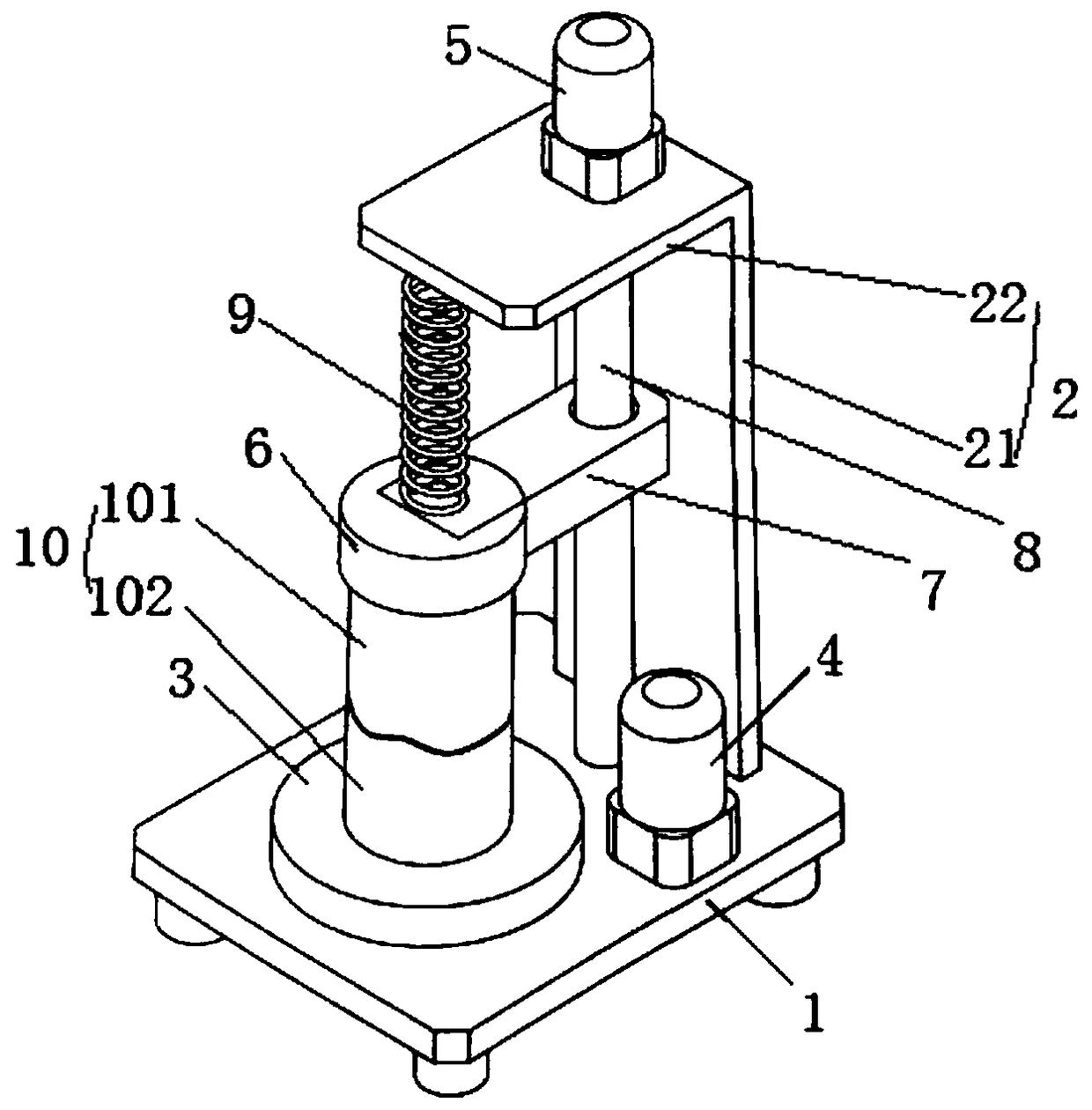
[0020] Please refer to figure 1 , the embodiment of the present invention provides an automatic control device for realizing the contact state of circular rock joints, including a base 1, a bracket 2, a turntable 3, a rotating motor 4, a lifting motor 5, a clamp 6, a spring 9, a clamp bracket 7 and Lift track 8.

[0021] The base 1 is located on the ground, the lower end of the support 2 is fixed on the base 1, the support 2 includes a horizontal plate 22 and a vertical plate 21, the lower end of the vertical plate 21 is fixed on one side of the base 1, and the upper end of the vertical plate 21 is connected to One side of the horizontal plate 22, and the horizontal plate 22 and the vertical plate 21 are integrally formed, and the horizontal plate 22 an...


PUM


Abstract

The invention discloses an automatic control device for realizing the circular rock joint contact state. The rock joint comprises a rock joint upper half block and a rock joint lower half block. The rock joint upper half block is arranged on the rock joint lower half block. The rock joint lower half block is directly put on a rotating disc. The rotating angle of the rotating disc is controlled bya rotating motor. The upper part of the rock joint upper half block is clamped and fixed by a clamp. The clamp is connected with a lifting motor which can drive the clamp to upward and downward move so as to drive the rock joint upper half block to move upward and downward in a reciprocating way. The position of the rock joint upper half block is fixed and then a spring along the vertical direction is inserted on the upper part of the clamp. The spring applies the vertical force to the rock joint to stabilize the rock joint. The circular rock joint contact state can be accurately controlled and the limitation that the existing method is only suitable for the square rock joint can be overcome.

Description

technical field [0001] The invention relates to the technical field of rock mechanics and engineering, in particular to an automatic control device and method for realizing the contact state of circular rock joints. Background technique [0002] Natural rock mass often contains a certain number of joints, which are prone to different degrees of disturbance under the action of external factors (such as earthquakes, blasting, etc.), which often show that there is a certain amount of staggered displacement between the two walls of the joints. At this time, the mechanical properties and hydraulic properties of rock joints change greatly. It is generally believed that the increase of the opening is one of the main reasons for the change of its mechanical properties and hydraulic properties. For rough rock joints, different stagger displacements often correspond to different openings. [0003] In production practice, circular joints are also commonly used as a test piece shape (...

Claims


Application Information

Patent Timeline
Patent Type & Authority Applications(China)
IPC IPC(8): G05B19/04
CPCG05B19/04
Inventor 唐志成
Owner CHINA UNIV OF GEOSCIENCES (WUHAN)
Learn More