Supercharge Your Innovation With Domain-Expert AI Agents!

Infrared touch device

An infrared touch and infrared light-emitting technology, which is applied in the field of packaging, can solve the problems of large operating body and inaccurate touch function, and achieve the effect of reducing space

Pending Publication Date: 2018-10-26
HEFEI LCFC INFORMATION TECH
View PDF0 Cites 0 Cited by
  • Summary
  • Abstract
  • Description
  • Claims
  • Application Information

AI Technical Summary

Problems solved by technology

Since the parallel placement of two laser light sources will increase the diameter of the overall module size, it can be seen that there are technical problems in the prior art that the touch function is inaccurate and the volume of the operating body is too large

Method used


Image

  • Infrared touch device
  • Infrared touch device

Examples


no. 1 example

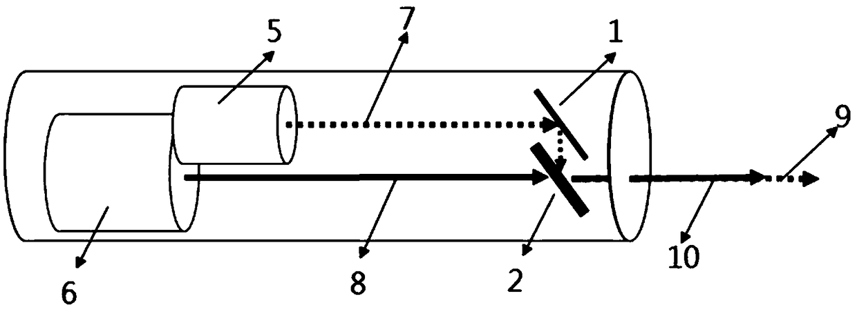
[0030] see figure 1 , the present invention provides an infrared touch device, comprising a body and an infrared light-emitting component, the body has a cavity for accommodating the infrared light-emitting component, and one side thereof is provided with a light emission port 12 for infrared light to pass through , in this embodiment, the body is set as a sleeve 11, of course, other options can be made, such as a square sleeve, a polygonal sleeve or a circular sleeve, which is not limited here.

[0031] Wherein, the infrared light-emitting component includes a first light-emitting component 5 capable of emitting visible infrared light, and a second light-emitting component 6 capable of emitting invisible infrared light;

[0032] A lens group is arranged between the infrared light-emitting component and the light emitting port 12, the first incident light 7 emitted by the first light-emitting component 5 passes through the lens group to form the first outgoing light 9, and the...

no. 2 example

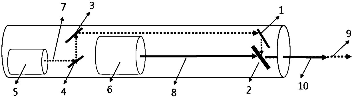
[0038] It should be noted here that the difference between the second embodiment and the first embodiment is that due to the difference in the specific arrangement of the illuminants, the number of lenses required and the positions of the arrangement also change, but finally the first outgoing light is realized. 9 and the optical path of the second outgoing light 10 have the same purpose, the same structure will not be further described here, and only the different features will be described accordingly.

[0039] In this embodiment, the lens group includes a first lens group and a second lens group, and the second light-emitting component 6 is arranged between the first light-emitting component 5 and the light emitting port 12; wherein, the first lens group is set between the second light emitting group and the light emitting port 12; the second lens group is arranged between the first light emitting assembly 5 and the second light emitting group; so that the first incident lig...


PUM


Abstract

The invention provides an infrared touch device, comprising a body and an infrared light emitting assembly. The body is equipped with a storage cavity for storing the infrared light emitting assembly.A light emitting opening convenient for infrared light to pass through is set at one side of the body. The infrared light emitting assembly comprises a first light emitting assembly capable of emitting visible infrared light, and a second light emitting assembly capable of emitting invisible infrared light. A lens group is set between the infrared light emitting assembly and the light emitting opening. First incident light emitted by the first light emitting assembly passes through the lens group to form first emergent light. Second incident light emitted by the second light emitting assemblypasses through the lens group to form second emergent light. Light paths of the first incident light and the second incident light are overlapped. A user can precisely control a specific direction ofthe invisible infrared light under the guide of visible infrared light, and a touch function of the invisible infrared light is exerted.

Description

technical field [0001] The invention relates to the field of packaging, in particular to an infrared touch device. Background technique [0002] Visible infrared light has the function of marking, and invisible infrared light can be triggered through the matching of IR camera through its touch function. The light spots that come out cannot be focused on the same position. In the process of touch operation, the touch is usually inaccurate and errors will occur. [0003] However, in the process of realizing the technical solutions in the embodiments of the present application, the inventors of the present application found that the above-mentioned technology has at least the following technical problems: [0004] The current solution is to separate the emitters of the two laser light sources from each other, and emit them in parallel, so that there will be some errors in the touch operation. Since the parallel placement of two laser light sources increases the diameter of th...

Claims


Application Information

Patent Timeline
IPC IPC(8): G06F3/042
CPCG06F3/042
Inventor 陈彦齐高彦彬徐崧哲黄建荣池咏伦王国纶
Owner HEFEI LCFC INFORMATION TECH
Features
  • R&D
  • Intellectual Property
  • Life Sciences
  • Materials
  • Tech Scout
  • Unparalleled Data Quality
  • Higher Quality Content
  • 60% Fewer Hallucinations
Learn More