Supercharge Your Innovation With Domain-Expert AI Agents!

Continuous die hanging punching device

A technology of die base and punch, which is applied in the field of continuous die, can solve the problems affecting the stamping accuracy, the position deviation of raw materials, etc., and achieve the effect of high economy, low production cost and prevention of position deviation

Inactive Publication Date: 2018-11-02
ANHUI KAICHENG ELECTRIC APPLIANCE CO LTD
View PDF0 Cites 0 Cited by
  • Summary
  • Abstract
  • Description
  • Claims
  • Application Information

AI Technical Summary

Problems solved by technology

[0003] During the continuous stamping process of the traditional continuous die, the impact of each punch will vibrate the raw material. Sometimes during continuous stamping, the position of the raw material stamped by the punch will be shifted, which will affect the stamping accuracy. For this reason, we propose A Continuous Die Lifting and Punching Device

Method used


Image

  • Continuous die hanging punching device
  • Continuous die hanging punching device
  • Continuous die hanging punching device

Examples


Embodiment Construction

[0018] The technical solutions in the embodiments of the present invention will be clearly and completely described below with reference to the accompanying drawings in the embodiments of the present invention. Obviously, the described embodiments are only a part of the embodiments of the present invention, but not all of the embodiments.

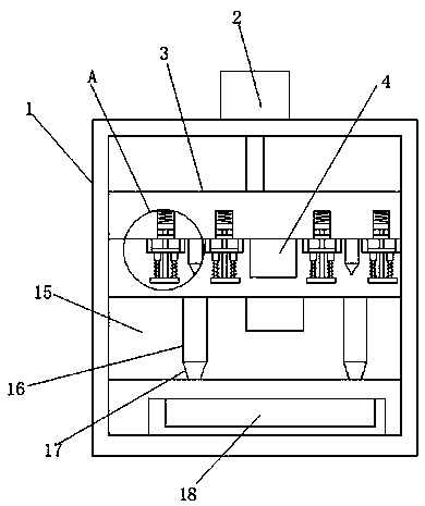
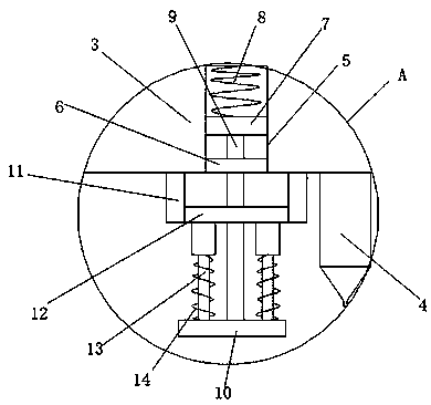
[0019] refer to Figure 1-3 , a continuous die punching device, comprising a frame 1, the top of the frame 1 is connected with a cylinder 2, the piston rod of the cylinder 2 is welded with an upper die seat 3, and the bottom end side wall of the upper die seat 3 is welded with a plurality of punches 4 , a lower die base 15 welded with the side walls on both sides of the frame 1 is installed below the upper die base 3, the top end of the lower die base 15 is provided with a plurality of concave dies 16, and the bottom end sidewall of the upper die base 3 is along its length direction. A plurality of grooves 5 are opened, the bottom end side ...


PUM


Abstract

The invention discloses a continuous die hanging punching device which comprises a frame. An air cylinder is connected to the top end of the frame, an upper die base is welded to a piston rod of the air cylinder, a plurality of male dies are welded to the side wall of the bottom end of the upper die base, a lower die base welded to the side walls of the two sides is installed below the upper die base, a plurality of female dies are arranged at the top end of the lower die base, a plurality of grooves are formed in the side wall of the bottom end of the upper die base in the length direction ofthe upper die base, a baffle is welded to the side wall of the bottom end of each groove, a sliding plate is in sliding connection between the two side walls of each groove, a first spring connectedwith the side wall of the corresponding groove is installed on the side wall of the side, far away from the corresponding baffle, of each sliding plate, a supporting rod is welded to the end, far awayfrom the corresponding first spring, of each sliding plate, and the other end of each supporting rod extends to the exterior of the corresponding groove to be provided with a pressing plate in a welded manner. By means of the continuous die hanging punching device, raw materials can be subjected to repeated punching quickly, extrusion fixation on accessories at the punching position can be achieved, position offset is prevented, and crushed materials obtained after punching can be collected.

Description

technical field [0001] The invention relates to the technical field of continuous molds, in particular to a continuous mold punching device. Background technique [0002] Continuous die refers to the cold stamping die in which the press uses strip-shaped stamping raw materials in one stamping stroke, and uses several different stations on a pair of molds to complete multiple stamping processes at the same time. The belt moves once at a fixed distance until the product is completed. [0003] During the continuous stamping process of the traditional continuous die, the impact of each punch will cause vibration to the raw material. Sometimes during continuous stamping, the position of the punch punched raw material will be shifted, which will affect the stamping accuracy. For this reason, we propose A continuous die hoisting and punching device is presented. SUMMARY OF THE INVENTION [0004] The purpose of the present invention is to propose a continuous die punching device...

Claims


Application Information

Patent Timeline
IPC IPC(8): B21D22/02B21D43/00B21D45/00
CPCB21D22/02B21D43/003B21D45/00
Inventor 张盼张建成朱同鹤
Owner ANHUI KAICHENG ELECTRIC APPLIANCE CO LTD
Features
  • R&D
  • Intellectual Property
  • Life Sciences
  • Materials
  • Tech Scout
  • Unparalleled Data Quality
  • Higher Quality Content
  • 60% Fewer Hallucinations
Learn More