
Cutting base of cutting machine tool and using method of cutting base

A cutting machine tool and cutting fluid technology, applied in the field of machine tools, can solve problems such as inseparability, affecting cutting processing efficiency, unfavorable follow-up processing, etc., and achieve the effect of increasing the discharge speed

Inactive Publication Date: 2018-11-02
张阳康
View PDF7 Cites 8 Cited by
  • Summary
  • Abstract
  • Description
  • Claims
  • Application Information

AI Technical Summary

Problems solved by technology

[0004] However, the above scheme has the following defects in use: when collecting waste chips and waste cutting fluid, the two cannot be separated, which is not conducive to subsequent processing. Cutting efficiency

Method used


Image

  • Cutting base of cutting machine tool and using method of cutting base
  • Cutting base of cutting machine tool and using method of cutting base
  • Cutting base of cutting machine tool and using method of cutting base

Examples


Embodiment Construction

[0024] The technical solutions in the embodiments of the present invention will be clearly and completely described below in conjunction with the embodiments of the present invention. Apparently, the described embodiments are only some of the embodiments of the present invention, not all of them. Based on the embodiments of the present invention, all other embodiments obtained by persons of ordinary skill in the art without making creative efforts belong to the protection scope of the present invention.

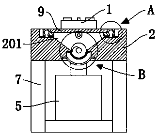
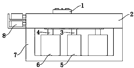
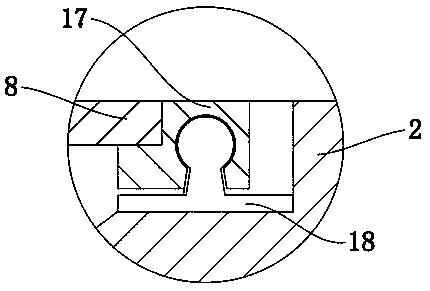
[0025] Such as Figure 1-5 As shown, a cutting base of a cutting machine tool includes a base body 2, the base body 2 is mounted on a bracket 7, a groove 201 is provided on the base body 2, and a groove 201 is movable inside the groove 201 for clamping. The workbench 1 for tightening the workpiece, the groove 201 is rotatably connected with a rotating shaft 10 and a screw 14, and the rotating shaft 10 and the screw 14 are fixedly connected with the output end of the stepping ...


PUM


Abstract

The invention discloses a cutting base of a cutting machine tool and a using method of the cutting base. The base comprises a base body; the base body is installed on a support; the base body is provided with a groove, then the groove is internally and movably provided with a working table for clamping a workpiece; the groove is internally and rotatably connected with a rotating shaft and a screwrod; the rotating shaft and the screw rod are separately and fixedly connected with an output end of a stepping motor; a first helical blade is welded and fixed on the rotating shaft; the screw rod isconnected with a lug plate by means of threads; the lug plate is welded and fixed at the bottom of the working table. According to the cutting base of the cutting machine tool, debris and cutting fluid can be separated from each other by means of filtration of a filter screen, and are stored in different areas; the debris drives the rotating shaft to rotate under the action of the stepping motor;the first helical blade and a second helical blade can be used for respectively pushing the debris in the groove into through holes formed at the two sides, so that the discharge speed of the debrisis accelerated, and the debris can be cleaned during the processing without affecting the cutting process.

Description

technical field [0001] The invention belongs to the technical field of machine tools, and in particular relates to a cutting base of a cutting machine tool and a using method thereof. Background technique [0002] Existing metal cutting machine tools will produce fine waste chips after cutting. Since there is no collection device, they are scattered on the ground, and need to be cleaned up after manual work, which consumes more working time for workers. When the machine is working, grinding The adjustment and cutting need to control different operation boxes, which cannot be integrated and conveniently operated. [0003] For this reason, the patent application number is CN201721354207.4, which discloses a metal cutting machine tool for mold production, including a runner and a spindle box. A processing port is provided, a motor is provided below the processing port, a through hole is provided at the lower right of the motor, and a residue collecting plate is arranged at the...

Claims


Application Information

Patent Timeline
Patent Type & Authority Applications(China)
IPC IPC(8): B23Q1/01B23Q3/06B23Q11/00
CPCB23Q1/01B23Q3/06B23Q11/0042
Inventor 张阳康
Owner 张阳康
Learn More