
Sleeving device for screw quenching

A set and screw technology, applied in quenching devices, furnaces, heat treatment equipment, etc., can solve the problems of inconvenient screw quenching operation, inconvenient batch installation of screws, and unstable screw installation, etc., to achieve the effect of convenient quenching treatment

Inactive Publication Date: 2018-11-02
丁茂明
View PDF0 Cites 0 Cited by
  • Summary
  • Abstract
  • Description
  • Claims
  • Application Information

AI Technical Summary

Problems solved by technology

The existing screw is inconvenient to install in batches, the installation of the screw is not firm, and it is inconvenient to use the quenching operation of the screw

Method used


Image

  • Sleeving device for screw quenching
  • Sleeving device for screw quenching
  • Sleeving device for screw quenching

Examples


Embodiment Construction

[0017] The preferred embodiments of the present invention will be described in detail below in conjunction with the accompanying drawings, so that the advantages and features of the present invention can be more easily understood by those skilled in the art, so as to define the protection scope of the present invention more clearly.

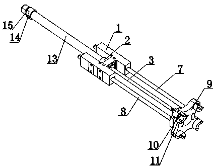
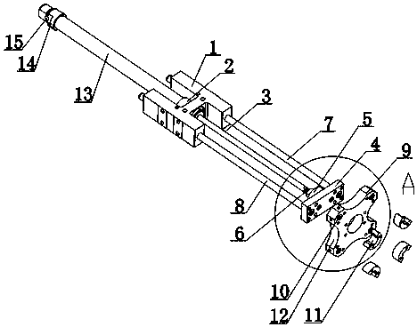
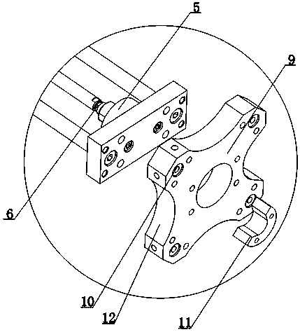
[0018] Such as Figure 1 to Figure 5 As shown, a set device for screw quenching includes a mounting block 1. The cross section of the mounting block 1 is H-shaped. The end of the rod 3 is provided with a fixed block 4, a first docking shaft 7 is provided between one end of the fixed block 4 and one side of the mounting block 1, and a first docking shaft 7 is provided between the other end of the fixed block 4 and the other side of the mounting block 1. There is a second docking shaft 8; the second docking shaft 8 is arranged in parallel with the first docking shaft 7; a mounting plate 9 is provided on the outwardly facing surface of the fixed blo...


PUM


Abstract

The invention discloses a sleeving device for screw quenching. The sleeving device for screw quenching comprises a mounting block, wherein the cross section of the mounting block is H-shaped; a butt-joint tube is arranged in the middle of the mounting block; one end of the butt-joint tube is connected with a butt-joint rod; a fixing block is arranged at an end of the butt-joint rod; a first butt-joint shaft is arranged between one end of the fixing block and one side of the mounting block; a second butt-joint shaft is arranged between the other end of the fixing block and the other side of themounting block; the second butt-joint shaft and the first butt-joint shaft are arranged in parallel; a mounting plate is arranged at the position of an outward surface of the fixing block; the periphery position of the mounting plate is provided with a sleeving groove and a magnetic attraction seat; the cross section of the magnetic attraction seat is semicircular; the magnetic attraction seat isattracted to the position of an outward surface of the mounting plate; the other end of the butt-joint tube is connected with another butt-joint tube; and the fixing block is connected with the mounting plate through a fixing bolt. The magnetic attraction seat can sleeve the outer peripheral surface of a screw and is attracted to the mounting plate, and therefore, the screw can be mounted firmly.

Description

technical field [0001] The invention relates to a screw processing device, in particular to a set device for screw quenching. Background technique [0002] The outer surface of the screw is a cylinder with a spiral groove or a cone with a conical spiral groove; the screw has different heads, such as a large flat screw, a hexagon socket screw, and the like. The existing screw rods are inconvenient to install in batches, the screw rods are not installed firmly, and it is inconvenient to use the quenching operation of the screw rods. Contents of the invention [0003] The present invention mainly solves the technical problems existing in the prior art, thereby providing a set device for screw quenching that can be set on the outer peripheral surface of the screw and adsorbed on the mounting plate through the magnetic suction seat, so that the screw can be installed more firmly . [0004] Above-mentioned technical problem of the present invention is mainly solved by followin...

Claims


Application Information

Patent Timeline
Patent Type & Authority Applications(China)
IPC IPC(8): C21D9/00C21D1/62
CPCC21D9/0068C21D1/62C21D9/0018
Inventor 丁茂明
Owner 丁茂明
Learn More