Glove machine needle drum worm structure

A technology of glove machine and worm, which is applied in knitting, weft knitting, textiles and papermaking, etc. It can solve the problems of difficult adjustment and achieve the effects of low maintenance cost, high precision and convenient processing

Pending Publication Date: 2018-11-02
SHAOXING HAN XIANG PRECISION MACHINERY MFG
View PDF24 Cites 0 Cited by
  • Summary
  • Abstract
  • Description
  • Claims
  • Application Information

AI Technical Summary

Problems solved by technology

[0002] The worms in the prior art are usually two worms that are transverse and coaxially connected through a fixed shaft; since in the actual installation process, the worm wheel and the worm need to be meshed, the coaxial connection should come when a worm and When the worm gear meshes, the other worm and the worm gear are more difficult to adjust, and since both worm gears need to turn inwards (i.e., one worm gear turns forward, the other worm wheel turns reversely), since the worms are connected coaxially, the worms also need to be Make a forward rotation and a reverse rotation (that is, the directions of the helices in the structure are different)

Method used


Image

  • Glove machine needle drum worm structure
  • Glove machine needle drum worm structure
  • Glove machine needle drum worm structure

Examples


Embodiment Construction

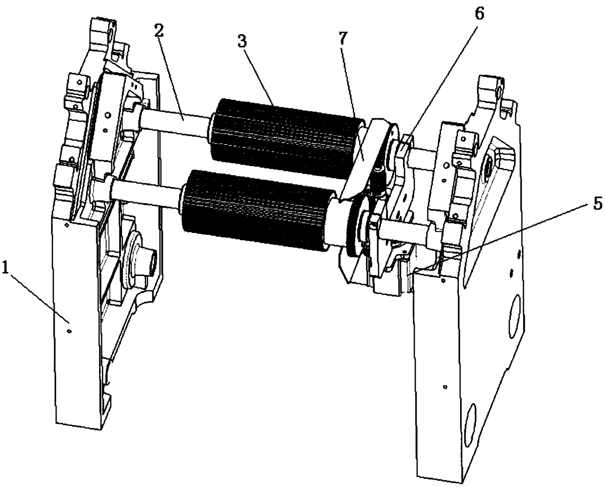
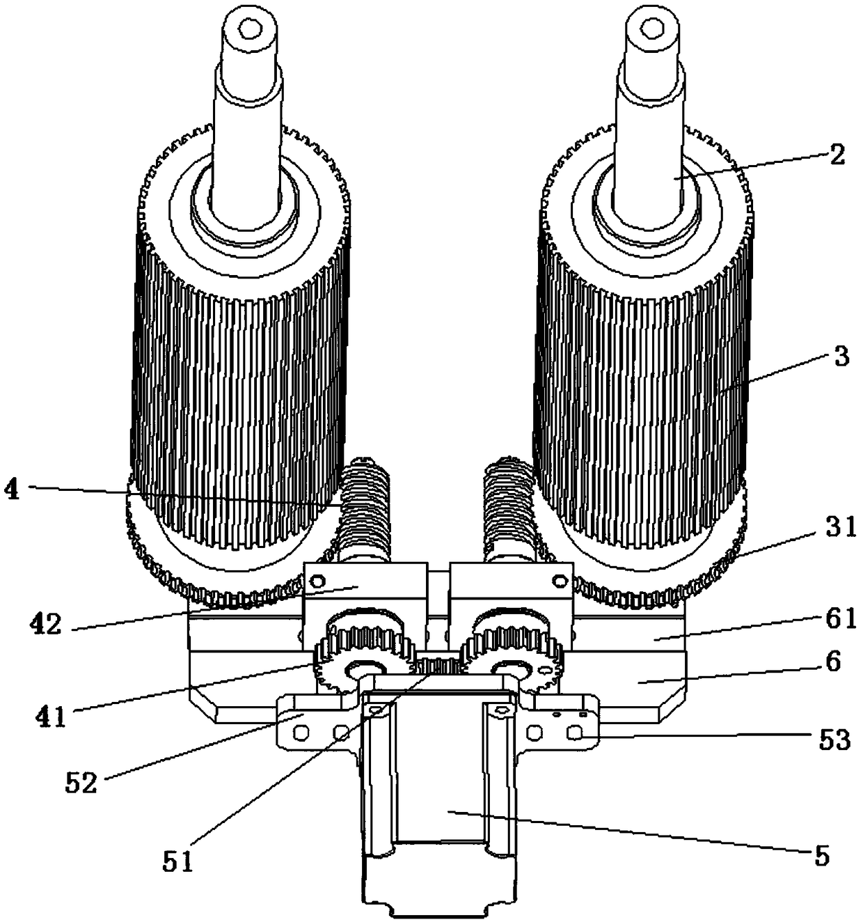
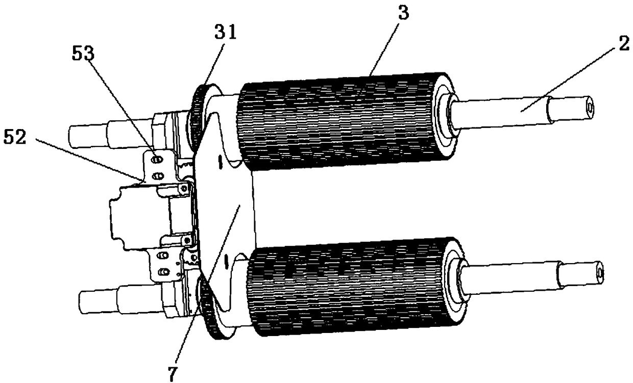
[0021] Combine below Figure 1-5 For further explanation, a glove machine needle drum and worm structure includes two wall panels 1, two needle drums 3, two worms 4, a motor 5, two worm gears 41, motor gears 51, and two worm seats 42 and base plate 6, fixed shaft 2 is installed on wall plate 1, needle drum 3 is installed on fixed shaft 2 through bearing 43, worm gear 31 is installed on needle drum 3, base plate 6 is installed on fixed shaft 2, motor base plate 52 is provided with The second chute 53, the motor bottom plate 52 and the bottom plate 6 are slidably connected through the second chute 53, the setting of the second chute 53 enables the motor 5 to move back and forth, that is, the motor gear 51 can move back and forth to compress the worm gear 41, when After adjustment, use screws to fix the motor bottom plate 52 on the bottom plate 6; the motor 5 is provided with a motor shaft, the motor shaft is provided with a motor gear 51, and the bottom plate 6 is provided with ...


PUM


Abstract

The invention relates to the field of glove machine parts, in particular to a glove machine needle drum worm structure. The glove machine needle drum worm structure comprises a wall plate; a fixed shaft is arranged on the wall plate; a needle drum is arranged on the fixed shaft; a worm wheel is arranged on the needle drum; a bottom plate is arranged on the fixed shaft; a motor is arranged on the bottom plate through a motor bottom plate; a motor shaft is arranged on the motor; a motor gear is arranged on the motor shaft; a horizontal groove is formed in the bottom plate; the horizontal grooveis in sliding connection with worm bases; a worm is arranged on the worm base; the worm and the worm wheel are arranged correspondingly; a worm gear is arranged below the worm; and the worm gear and amotor gear are arranged correspondingly. The horizontal groove is provided, so that the worm base can slide in the horizontal groove left and right; and two worm bases are commonly arranged on the horizontal groove, and the worm is arranged on each worm base. The invention provides the glove machine needle drum worm structure convenient to mount.

Description

technical field [0001] The invention relates to the field of glove machine parts, in particular to a needle-drum worm structure of a glove machine. Background technique [0002] The worms in the prior art are usually two worms that are transverse and coaxially connected through a fixed shaft; since in the actual installation process, the worm wheel and the worm need to be meshed, the coaxial connection should come when a worm and When the worm gear meshes, the other worm and the worm gear are more difficult to adjust, and since both worm gears need to turn inwards (i.e., one worm gear turns forward, the other worm wheel turns reversely), since the worms are connected coaxially, the worms also need to be Make a positive rotation and a reverse rotation (that is, the directions of the helical patterns in the structure are different). Contents of the invention [0003] The present invention hopes to provide a needle-drum worm structure of a glove machine to solve the deficien...

Claims


Application Information

Patent Timeline
Patent Type & Authority Applications(China)
IPC IPC(8): D04B15/16
CPCD04B15/16
Inventor 李鸣黄志升宋同义
Owner SHAOXING HAN XIANG PRECISION MACHINERY MFG
Why Eureka
Try Eureka