Burner fire cover, burner and gas stove

A burner and fire cover technology, which is applied to burners, gas fuel burners, combustion methods, etc., can solve the problems of uneven mixing of gas and air, poor flame shape, and large burner volume, and is easy to disassemble and assemble. The effect of cleaning, good shape and uniform flame

Pending Publication Date: 2018-11-02
QINGDAO HAIER DISHWASHER
View PDF8 Cites 2 Cited by
  • Summary
  • Abstract
  • Description
  • Claims
  • Application Information

AI Technical Summary

Problems solved by technology

[0002] Existing single-ring fire combustion systems such as figure 1 As shown, burner head 1 and fire cover 2 are generally used to realize combustion. The gas and primary air pass through the cavity of burner head 1, and after being premixed in the cavity, they are directly burned through fire outlet 3 of fire cover 2, because the gas Inhomogeneous mixing with air, and different outlet pressures of each fire outlet 3, resulting in poor flame shape, insufficient combustion, and uneven flames
Moreover, the fire outlet grooves 3 on the traditional burner are all circular holes. After a long time of use, carbon deposits are easy to occur, and it is very troublesome to clean.
[0003] In addition, in order to be able to detect the temperature of the bottom of the pot in real time and realize the anti-dry function, some existing burners install a temperature-sensing probe on the burner. At present, a temperature-sensing probe is generally installed on a double-ring burner, such as Chinese patent number 200710145761.6 The patent disclosed a double-ring combustion system for preventing dry burning, including a burner, a fire cover seat is installed on the burner, the outer ring fire cover is installed on the fire cover seat, and the inner ring fire cover is directly installed on the burner. There is a through hole at the center of the inner ring fire cover and the burner, and an anti-dry temperature sensor is installed in the through hole. The structure of the annular support seat is to supply gas to the outer ring mixing chamber and the inner ring mixing chamber respectively, which makes its structure complex, the volume of the burner is large, and the shape is relatively cumbersome, and the traditional burner structure needs to be greatly modified. change

Method used


Image

  • Burner fire cover, burner and gas stove
  • Burner fire cover, burner and gas stove
  • Burner fire cover, burner and gas stove

Examples


Embodiment Construction

[0034] Below in conjunction with accompanying drawing and specific embodiment the present invention is described in further detail:

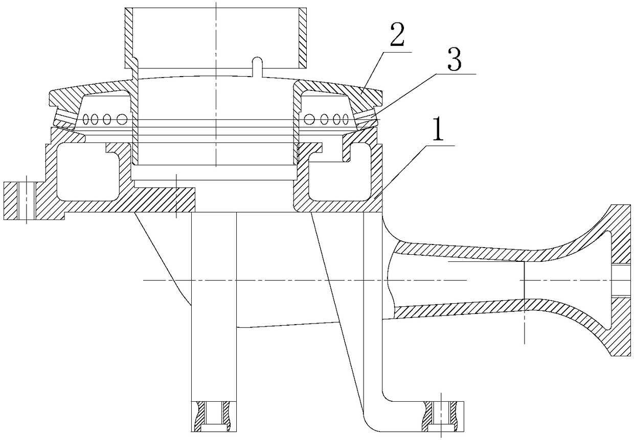
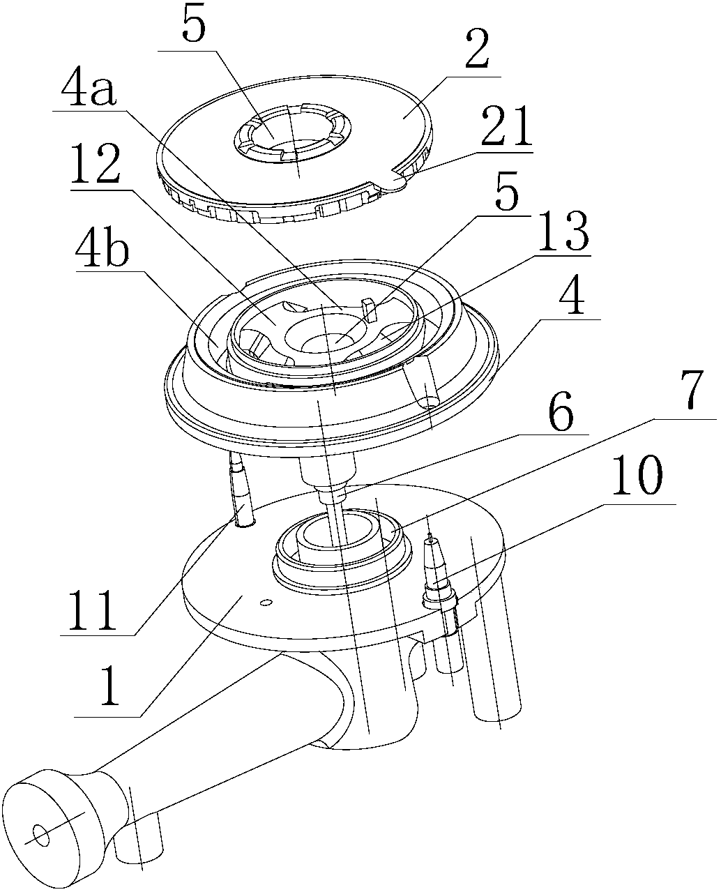
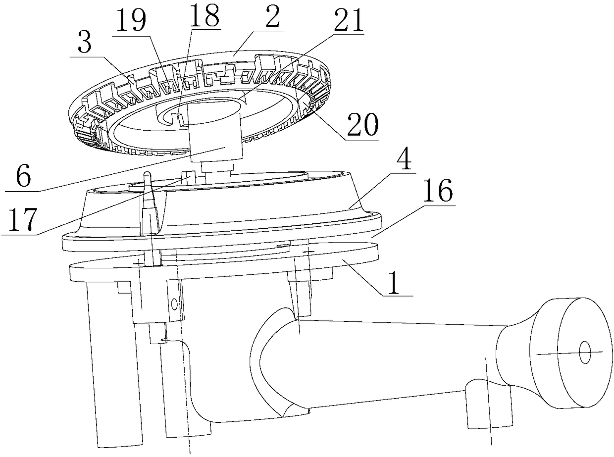
[0035] Such as Figure 2 to Figure 4 As shown, a burner provided by the present invention is a single-ring burner, including a burner head 1, a fire cover 2 and a fire cover seat 4, the fire cover seat 4 is plugged and installed on the burner head 1, and the fire cover 2 is plugged Installed on the fire cover seat 4, a circle of fire outlet grooves 3 is set on the side wall outside the fire cover 2, and the combustion gas is burned after being sprayed out by several fire outlet grooves 3. There is a through hole 5 in the center of the fire cover 2 , the fire cover seat 4 and the burner 1 , and the anti-dry burning sensor 6 is fixed through the through hole 5 . The bottom of the anti-dry sensor 6 is fixedly installed on the burner 1 through a fixed structure such as a bracket, and can also be fixedly installed on the bottom shell of the gas rang...


PUM


Abstract

The invention relates to a burner fire cover, a burner and a gas stove. A fire cover base is arranged on a furnace end, the fire cover is arranged on the fire cover base, a fire outlet groove is formed in the fire cover, a penetrating through hole is formed in the centers of the fire cover, the fire cover base and the furnace end, a dry-burning-prevention sensor is arranged in the through hole, aninner ring cavity and an outer ring cavity are formed in the fire cover base, the inner ring cavity is annularly arranged around the through hole, a gas outlet of the furnace end communicates with the inner ring cavity, the fire outlet groove communicates with the outer ring cavity, the inner ring cavity and the outer ring cavity communicate through a connection channel, and the longitudinal section of the fire outlet groove is square. The whole structure is simple, dismounting, mounting and cleaning are easy, gas sufficient mixing is facilitated, flames are more uniform, combustion is more sufficient, and the combustion effect is better.

Description

technical field [0001] The invention relates to a gas stove, in particular to a single-ring burner installed on the gas stove and having the function of preventing dry burning, and at the same time relates to a burner fire cover installed on the burner. Background technique [0002] Existing single-ring fire combustion systems such as figure 1 As shown, burner head 1 and fire cover 2 are generally used to realize combustion. The gas and primary air pass through the cavity of burner head 1, and after being premixed in the cavity, they are directly burned through fire outlet 3 of fire cover 2, because the gas Inhomogeneous mixing with air and different outlet pressures of each fire outlet 3 lead to poor flame shape, insufficient combustion, and uneven flames. Moreover, the fire outlet grooves 3 on the traditional burner are all circular holes. After a long time of use, carbon deposits are easy to occur, and it is very troublesome to clean up. [0003] In addition, in order t...

Claims


Application Information

Patent Timeline
Patent Type & Authority Applications(China)
IPC IPC(8): F23D14/46F23D14/72F23D14/02F23D14/26
CPCF23D14/02F23D14/26F23D14/46F23D14/72
Inventor 陈雄王明琴
Owner QINGDAO HAIER DISHWASHER
Why Eureka
Try Eureka