
Water and electricity separation energy-saving water dispenser

A technology for separation of water and electricity and water dispenser, applied in the fields of electric water dispenser and electric water heater, can solve the problems of increasing process difficulty, easy to produce scale, and high power consumption, and achieve the effects of scientific and reasonable water flow system, small circulation resistance, and improved thermal efficiency.

Inactive Publication Date: 2012-02-08
GUANGDONG BILI DRINKING WATER EQUIPMENT CO LTD
View PDF1 Cites 0 Cited by
  • Summary
  • Abstract
  • Description
  • Claims
  • Application Information

AI Technical Summary

Problems solved by technology

In the energy-saving water dispenser with the above structure, since the electric heating tube is arranged inside the electric water boiler (namely: the water storage liner), if the electric heating tube burns out and bursts, electric leakage will occur, and the insulating material magnesium powder of the electric heating tube will fall into the water , affect the water quality, and, the built-in electric heating tube heating method is easy to generate scale on the inner wall of the electric water boiler or the surface of the electric heating tube, which will not only affect the heat transfer efficiency, but also cause the electric heating tube to burn out easily
[0003] For this reason, there are also people who install the electric heating tube on the outside of the electric water boiler (that is: the water storage liner), such as: the electric heating tube is installed on the bottom of the electric water boiler; that is: adopt an external electric heating plate heating method; the design Although the electric water dispenser has solved the potential safety hazard that water and electricity do not separate to a certain extent, it still has the following deficiencies: (1) because this heating method still adopts traditional electric heating tube (resistance wire) heating , the electric heating tube is externally heated, and most of its heat will be lost to the air, making it consume a lot of power. For this reason, it is necessary to add a thick insulation material, which not only increases the difficulty of the manufacturing process, but also leads to an increase in cost; (2) Traditional electric heating tube (resistance wire) heating will easily generate scale in the electric water boiler, which will not only affect the heat conduction efficiency, but also cause the electric heating tube to burn out easily; (3) Traditional built-in or external electric heating tube heating type The water boiler can only be used to boil water, but not to magnetize and activate water, and cannot prevent scale

Method used


Image

  • Water and electricity separation energy-saving water dispenser
  • Water and electricity separation energy-saving water dispenser
  • Water and electricity separation energy-saving water dispenser

Examples


Embodiment 1

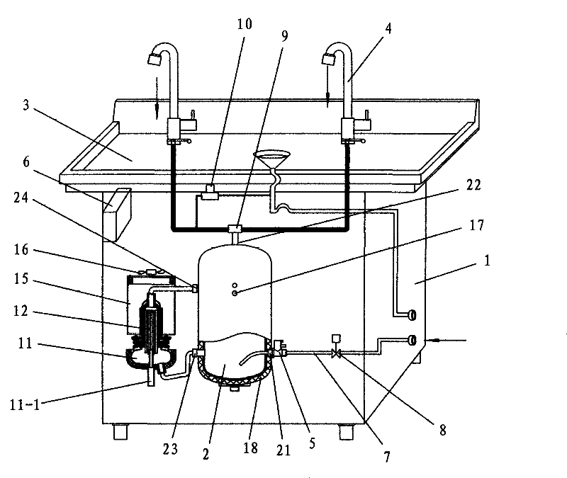
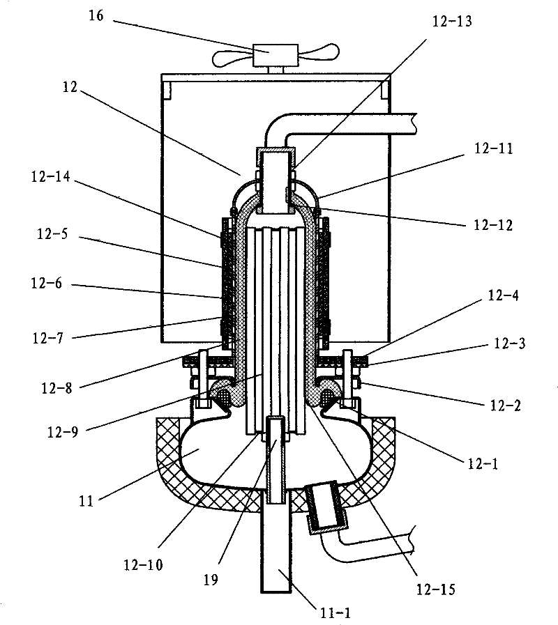
[0025] Embodiment one: if figure 1As shown, a water and electricity separation energy-saving water dispenser includes a water dispenser cabinet 1, on which a water storage tank 2, a water receiving basin 3, a water outlet connector 9, a water faucet 4, a safety valve 5 and an electric control device 6 are installed. , the lower part of the water tank 2 has a water inlet 21, and its upper part has a water outlet 22, the water inlet 21 is connected to the water inlet pipeline 7, the safety valve 5 and the water inlet solenoid valve 8 are installed on the water inlet pipeline 7, and the water outlet 22 is connected There is a water outlet joint 9, and the water opening faucet 4 and the drainer 10 are respectively connected to the water outlet joint 9. The water opening faucet 4 is a water and electricity linkage faucet. The program is opened and closed synchronously, so that the water storage tank 2 maintains a normal pressure state, and an independent boiling water tank 11 is al...

Embodiment 2

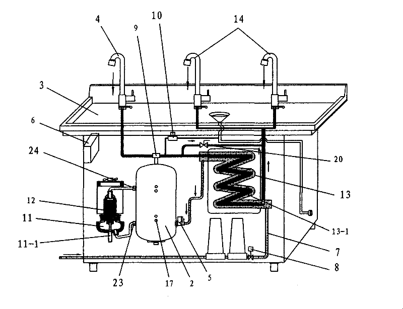
[0031] Embodiment two: if image 3 As shown, this embodiment is similar to Example 1, the only difference is that a heat exchanger 13 is also installed on the water inlet pipeline 7 of the water tank, and one end of the inner tube 13-1 of the heat exchanger 13 is connected to the water outlet connector. 9 is connected, and the other end is connected with warm water faucet 14, and warm water faucet 14 is hydropower linkage valve, so that it cooperates with electric control device 6, makes water storage tank 2 maintain normal pressure state, and the inner pipe 13-1 of heat exchanger 13 two The end is also connected with a temperature regulating valve 20; by adding a heat exchanger 13 on the water dispenser, utilizing the principle of the inner tube 13-1 of the heat exchanger for hot water and the outer tube for cold water (tap water), the hot water dissipates heat and the cold water absorbs heat. , can not only provide people with warm water for instant drinking, but also improv...


PUM


Abstract

The invention relates to an energy-saving water dispenser with separation of water and electricity. A water tank and an electric control device are installed on the box body. At normal pressure, an independent boiling water tank is fixed on the box, and an internal heating electromagnetic heater is installed on the boiling water tank. There is a circulating water outlet on the lower part of the tank, and a circulating water inlet on the upper part. The circulating water outlet is connected to the water inlet hole at the bottom of the boiling water tank. The circulating water inlet is connected to the inner tank of the internal heating electromagnetic heater. Electrically connected with the electric control device. This type of water dispenser, by independently setting the boiling water tank and its internal heating electromagnetic heater outside the water storage tank, the water flows in the boiling water tank and the internal heating electromagnetic heater in a cycle from bottom to top, which can improve Thermal efficiency, water and electricity separation heating, it is difficult to generate scale in the water dispenser, the heated and boiled water will be well activated and magnetized, and it has the advantages of good drinking water taste, good health and heating safety.

Description

technical field [0001] The invention relates to the technical field of electric water dispensers and electric water boilers, in particular to an energy-saving water dispenser heated by separating water from electricity. , so that the water flow can circulate from bottom to top in the boiling water tank body and the internal heating electromagnetic heater, which can obviously improve its thermal efficiency. Background technique [0002] At present, most of the electric water dispensers sold on the market use electric heating tubes (resistance wires) to directly heat the water in the electric water heaters inside the housing of the water dispenser, that is, the built-in electric heating tubes are used for heating. The structure is shown in the Chinese utility model patent. No.: 02271829.X, titled "energy-saving drinking water dispenser"; this patent was applied by the applicant on July 18, 2002, for an energy-saving drinking water dispenser for heating tap water to boiling wat...

Claims


Application Information

Patent Timeline
Patent Type & Authority Patents(China)
IPC IPC(8): A47J31/00
Inventor 巫宗权梁裕镳李志春
Owner GUANGDONG BILI DRINKING WATER EQUIPMENT CO LTD
Learn More