
Optical fiber temperature and pressure sensor for double-cavity structure and a preparation method thereof

A technology of pressure sensor and optical fiber temperature, which is applied in the direction of physical/chemical change thermometer, thermometer, and measurement of the change force of the optical property of the material when it is stressed, which can solve the problem of complex sensor structure and high sensor packaging requirements , difficult to manufacture and other issues

Pending Publication Date: 2018-11-02
北京东方锐择科技有限公司
View PDF11 Cites 8 Cited by
  • Summary
  • Abstract
  • Description
  • Claims
  • Application Information

AI Technical Summary

Problems solved by technology

[0004] However, the above-mentioned solution of adding a fiber grating to measure temperature has higher requirements on the packaging of the sensor, especially the optical fiber in the grating part needs to be in a free state without stress
Although the combination of intrinsic and extrinsic F-P cavity can obtain temperature and pressure at the same time, the sensor structure is complex and difficult to manufacture

Method used


Image

  • Optical fiber temperature and pressure sensor for double-cavity structure and a preparation method thereof
  • Optical fiber temperature and pressure sensor for double-cavity structure and a preparation method thereof
  • Optical fiber temperature and pressure sensor for double-cavity structure and a preparation method thereof

Examples


preparation example Construction

[0062] A method for preparing an optical fiber temperature and pressure sensor with a dual-cavity structure, said method comprising the following steps:

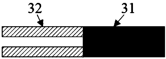
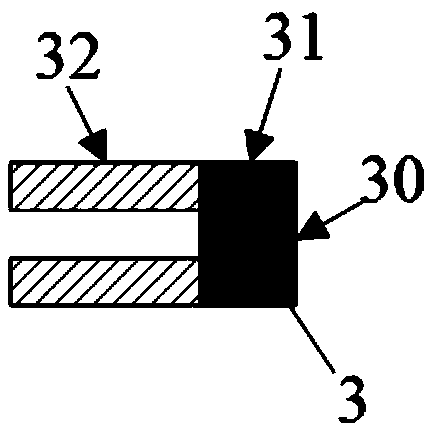
[0063] The second capillary 32 and a section of optical fiber 31 are fused together, and the optical fiber 31 is thinned and ground to a required length to form an intrinsic type F-P cavity 3;

[0064] Insert the incident component 1, the intrinsic F-P cavity 3, and the reflective component 2 into the first capillary 5, and reasonably control their distance to form an extrinsic F-P cavity 4, which is fixedly connected to form a dual-cavity optical fiber temperature and pressure sensor.

[0065] The way of the fixed connection is glue or welding.

[0066] The technical solution for inserting the incident component 1, the intrinsic F-P cavity 3, and the reflective component 2 into the first capillary 5, reasonably controlling the distance thereof, and forming the extrinsic F-P cavity 4 includes the following steps: The incide...

Embodiment 1

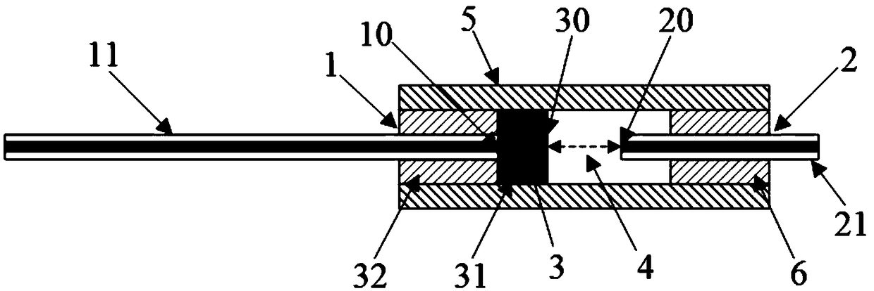
[0072] Embodiment 1 provides an optical fiber temperature and pressure sensor with a dual-cavity structure. Such as figure 1 as shown, figure 1 It is a structural schematic diagram of an optical fiber temperature and pressure sensor with a dual-cavity structure in Embodiment 1 of the present invention, Figure 2A to Figure 2E It is a schematic diagram of the sensor preparation process in Example 1 of the present invention.

[0073] The optical fiber temperature and pressure sensor with dual cavity structure includes: an intrinsic F-P cavity 3 , an incident component 1 , a reflective component 2 , an extrinsic F-P cavity 4 , and a first capillary 5 .

[0074] The intrinsic type F-P cavity 3 is formed by fusing a second capillary 32 and a section of optical fiber 31; the incident component 1 includes an incident optical fiber 11 for guiding the incidence of coherent light beams; the incident optical fiber 11 is inserted into the intrinsic type F-P cavity 3 The second capillar...

Embodiment 2

[0084] Embodiment 2 provides an optical fiber temperature and pressure sensor with a dual-cavity structure. Such as image 3 as shown, image 3 It is a structural schematic diagram of an optical fiber temperature and pressure sensor with a dual-cavity structure in Embodiment 2 of the present invention. Figure 4A to Figure 4EIt is a schematic diagram of the sensor preparation process of Example 2 of the present invention.

[0085] The optical fiber temperature and pressure sensor with dual cavity structure includes: an intrinsic F-P cavity 3 , an incident component 1 , a reflective component 2 , an extrinsic F-P cavity 4 , and a first capillary 5 .

[0086] The intrinsic type F-P cavity 3 is located between the incident component 1 and the reflective component 2, and is formed by fusing a second capillary 32 and a section of optical fiber 31; the incident component 1 includes an incident optical fiber 11 for guiding coherent The incidence of the light beam, the incident opt...


PUM


Abstract

The invention provides an optical fiber temperature and pressure sensor for a double-cavity structure and a preparation method thereof. The sensor comprises an incoming component, which is provided with an incoming optical fiber for guiding the incidence of related light beams; a reflecting component, which comprises a reflecting optical fiber used for keeping a reasonable distance with the incoming component so as to form an intrinsic type F-P cavity and a non-intrinsic type F-P cavity. The intrinsic type F-P cavity is formed by welding a second capillary tube and a section of optical fiber;the non-intrinsic type F-P cavity is formed by keeping reasonable distance with the end surface of the incoming component or the reflecting component; a first capillary tube is fixedly connected withthe components. According to reflection of the cavity length of the non-intrinsic type F-P cavity to the related light beams, the measuring temperature and pressure can be obtained; according to the reflection of the cavity length of the intrinsic type F-P cavity to the related light beams, the measuring temperature can be obtained; accurate measurement pressure is obtained after temperature compensation. The invention is advantageous in that the temperature compensation is carried out on the non-intrinsic cavity through the intrinsic cavity, obtaining accurate pressure value; the structure issimple and manufacturing is easy.

Description

technical field [0001] The invention relates to an optical fiber temperature and pressure sensor, in particular to an optical fiber temperature and pressure sensor with a double-cavity structure and a preparation method thereof. Background technique [0002] Optical fiber Fabry-Perot sensor is an interference sensor formed by F-P cavity constructed by optical fiber and capillary, which can be divided into intrinsic type and extrinsic type. Among them, the intrinsic F-P sensor (Intrinsic Fabry-Perot Interferometer, IFPI) uses the optical fiber itself to form an F-P cavity with a cavity length of L, and the extrinsic F-P sensor (Extrinsic Fabry-Perot Interferometer, EFPI) uses two optical fiber end faces (two The air gap between the end faces coated or uncoated) constitutes an F-P cavity with a cavity length L. When the coherent light beam enters the F-P cavity along the fiber, the fiber returns along the original path after being reflected by the two ends of the F-P cavity a...

Claims


Application Information

Patent Timeline
Patent Type & Authority Applications(China)
IPC IPC(8): G01K11/32G01L1/24
CPCG01K11/32G01L1/24
Inventor 何向阁李谊军杨健高玉倩连子龙
Owner 北京东方锐择科技有限公司
Learn More