
A mobile clamping device for enameled wire

A clamping device and enameled wire technology, which is applied in the manufacture of electrical components, circuits, cables/conductors, etc., can solve the problems such as the inability of the pay-off roller to fall, the deformation of the rubber block, and the damage of the pay-off roller. The effect of protecting safety, ensuring continuous use and convenient rotation

Active Publication Date: 2020-04-03
ANHUI CHUNHUI INSTR CABLE GROUP
View PDF8 Cites 0 Cited by
  • Summary
  • Abstract
  • Description
  • Claims
  • Application Information

AI Technical Summary

Problems solved by technology

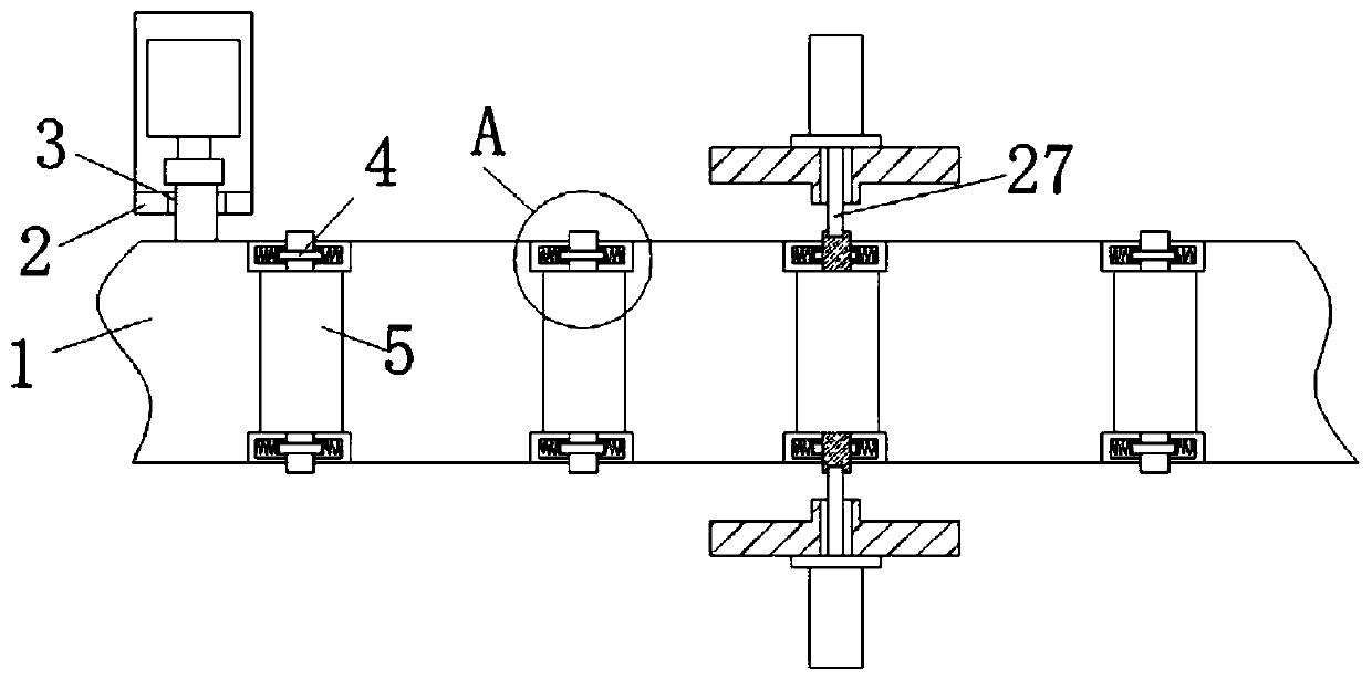
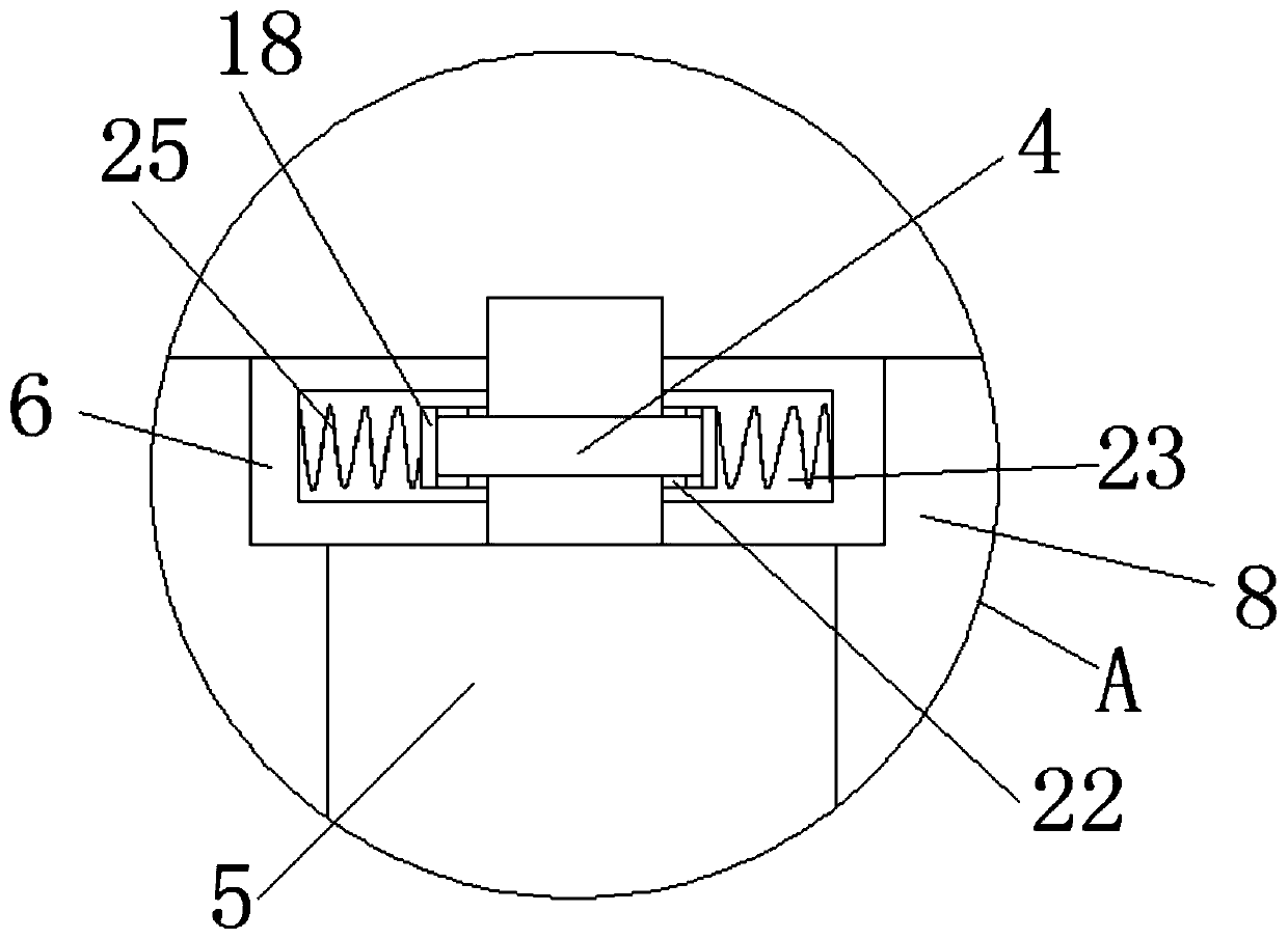
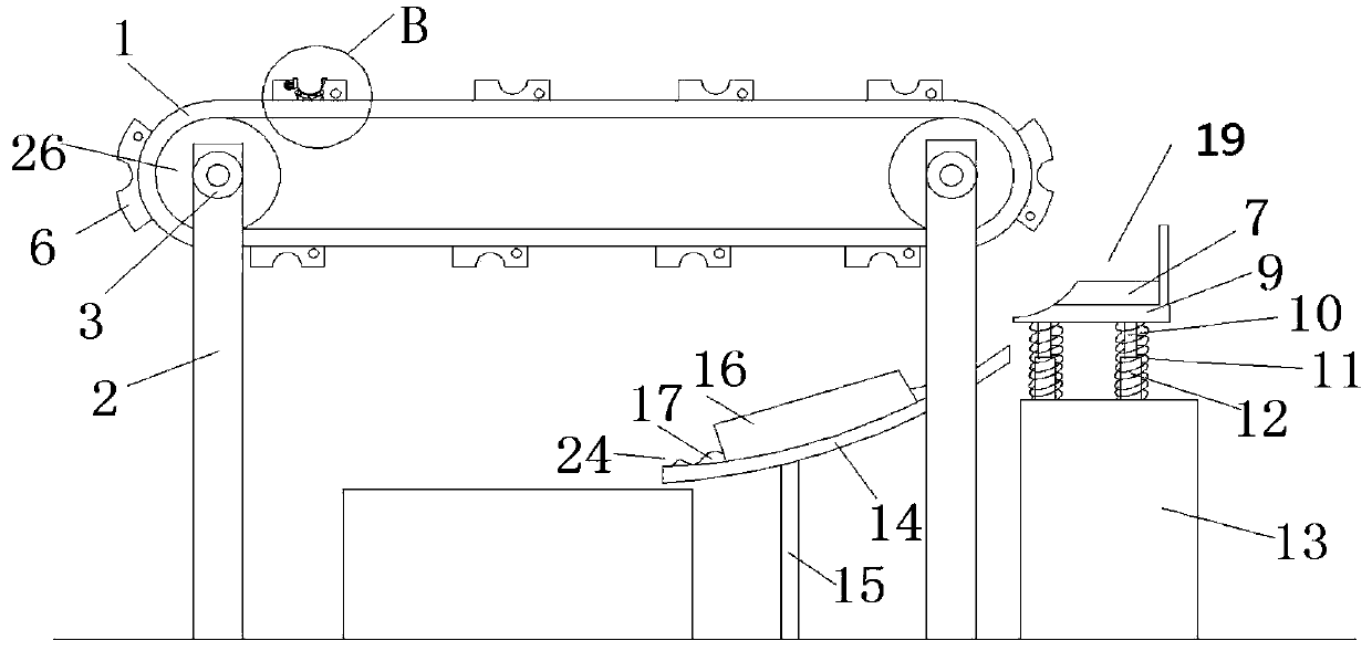
[0004] The purpose of the present invention is to solve the deformation of the rubber block in the prior art, and the deformation will make the ring-shaped bumps clamped tighter, resulting in the failure of the pay-off drum to fall, which will affect the next step of the device and the release. The wire drum falls directly from the conveyor belt, which easily damages the wire drum to be paid off and increases the cost of the device. A mobile enameled wire clamping device is proposed

Method used


Image

  • A mobile clamping device for enameled wire
  • A mobile clamping device for enameled wire
  • A mobile clamping device for enameled wire

Examples


Embodiment Construction

[0022] The technical solutions in the embodiments of the present invention will be clearly and completely described below in conjunction with the accompanying drawings in the embodiments of the present invention. Obviously, the described embodiments are only a part of the embodiments of the present invention, rather than all the embodiments.

[0023] In the description of the present invention, it should be understood that the terms "upper", "lower", "front", "rear", "left", "right", "top", "bottom", "inner", " The orientation or positional relationship indicated by “outside” is based on the orientation or positional relationship shown in the drawings, and is only for the convenience of describing the present invention and simplifying the description, and does not indicate or imply that the device or element referred to must have a specific orientation to The specific azimuth structure and operation cannot be understood as a limitation of the present invention.

[0024] Reference ...


PUM


Abstract

The invention discloses a movable clamping device for an enameled wire. The movable clamping device comprises two groups of supporting legs, a driving roller, a conveyor belt, rubber placing blocks, apush rod and rollers waiting for paying-off, wherein circular through holes are formed in the opposite sides of each group of supporting legs, and the wall hole of each circular through hole is fixedly connected with a first rolling bearing; the inner walls of the two first rolling bearings are fixedly connected with shaft walls at two ends respectively; the surfaces of two driving rollers are connected with the lower surface of the conveyor belt in a rolling manner respectively; the rubber placing blocks are arranged into two lines on the conveyor belt, and the two lines of rubber placing blocks are fixedly arranged on the left side and right side of the conveyor belt respectively; the two lines of rubber placing blocks are arranged in a one-to-one correspondence manner; and an arc-shaped through groove is formed in the upper surface of each rubber placing block. The movable clamping device is convenient in operation, the safety of the rollers waiting for paying-off is protected, continuous use of the rollers waiting for paying-off can be guaranteed, the using cost of the device is reduced, and the rollers waiting for paying-off can fall off extremely conveniently to guarantee that the following work of the device is not influenced.

Description

Technical field [0001] The invention relates to the technical field of enameled wire processing equipment, in particular to a mobile clamping device for enameled wire. Background technique [0002] Enameled wire is a main type of winding wire. It consists of a conductor and an insulating layer. After the bare wire is annealed and softened, it is painted and baked many times, but it must be produced that meets the requirements of the standard and the requirements of the customers. The product is not easy. It is affected by the quality of raw materials, process parameters, production equipment, environment and other factors. Therefore, the quality characteristics of various enameled wires are different, but they all have mechanical properties, chemical properties, electrical properties, and thermal properties. . [0003] After searching, the Chinese patent application No. CN 104658702 B discloses a mobile clamping device for enameled wire, which includes two sets of support legs, tr...

Claims


Application Information

Patent Timeline
Patent Type & Authority Patents(China)
IPC IPC(8): H01B13/00
CPCH01B13/0036
Inventor 沈必亮王晓春
Owner ANHUI CHUNHUI INSTR CABLE GROUP
Learn More