Intelligent garden irrigation device based on cloud computing
An irrigation device and cloud computing technology, applied in the field of gardens, can solve problems such as uneven irrigation and waste of a large number of resources of users, and achieve the effect of saving resources and being convenient to use
- Summary
- Abstract
- Description
- Claims
- Application Information
AI Technical Summary
Problems solved by technology
Method used
Image

Examples
Embodiment
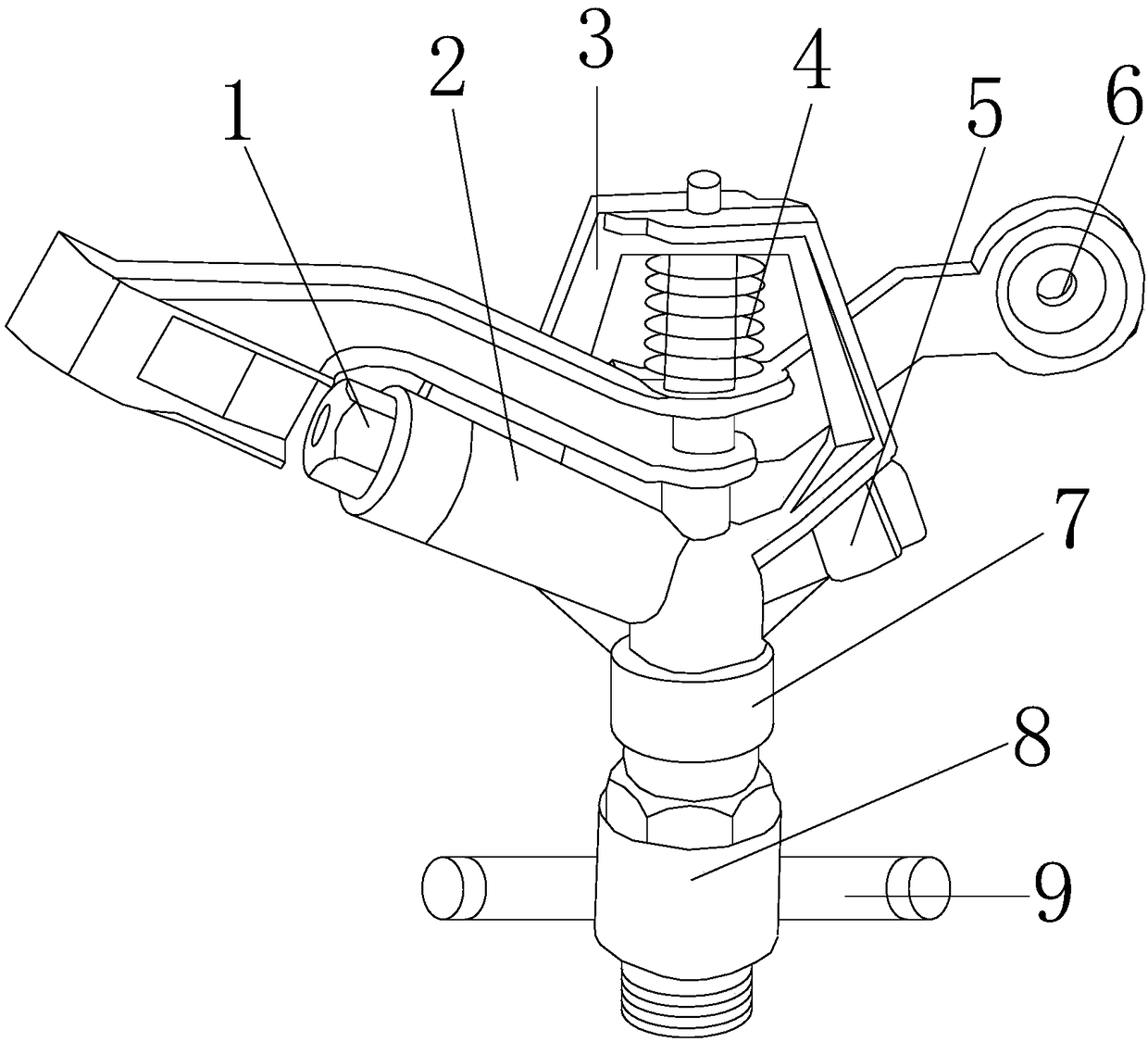
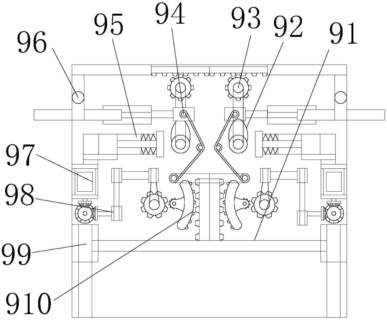
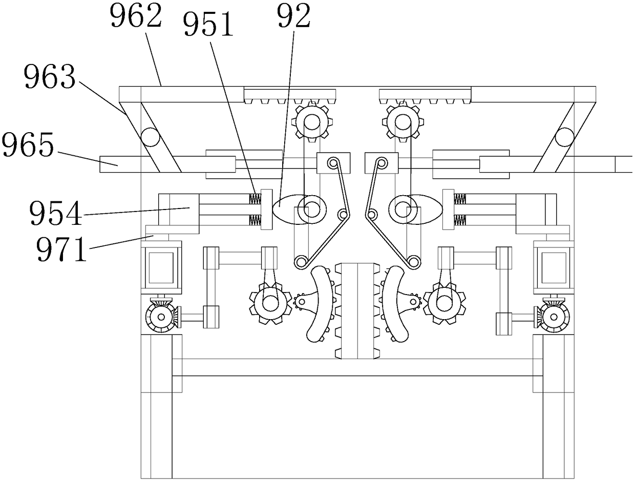
[0026] see Figure 1-Figure 5 , the present invention provides an intelligent garden watering device based on cloud computing, the structure of which includes a sprinkler head 1, a sprinkler pipe 2, a swivel frame 3, a damping spring 4, a water inlet 5, a mounting buckle 6, a rotating shaft 7, a connecting pipe 8, Telescoping mechanism 9, the water spray nozzle 1 is located at the top left side of the water spray pipe 2, and the water spray pipe 2 and the water spray nozzle 1 are an integrated structure;
[0027] The bottom of the water spray pipe 2 is provided with a connecting pipe 8, the connecting pipe 8 and the water spray pipe 2 are an integrated structure, the right side of the top of the connecting pipe 8 is fixedly provided with a water inlet 5, and the connecting pipe 8 is provided with a There is a rotating shaft 7, the rotating shaft 7 and the connecting pipe 8 adopt a clearance fit, the top of the connecting pipe 8 is provided with a rotating frame 3, the rotating...
PUM
 Abstract
Description
Claims
Application Information
 - Generate Ideas
- Intellectual Property
- Life Sciences
- Materials
- Tech Scout
- Unparalleled Data Quality
- Higher Quality Content
- 60% Fewer Hallucinations
Browse by: Latest US Patents, China's latest patents, Technical Efficacy Thesaurus, Application Domain, Technology Topic, Popular Technical Reports.
© 2025 PatSnap. All rights reserved.Legal|Privacy policy|Modern Slavery Act Transparency Statement|Sitemap|About US| Contact US: help@patsnap.com