
Computer optometry unit for ophthalmologic therapy

A technology of medical optometry, applied in the field of optometry, which can solve the problems affecting the accuracy of measurement, the single function of optometry equipment, and the complicated adjustment of the placement frame, so as to achieve the effect of improving accuracy, convenient adjustment, and reasonable and reliable performance

Inactive Publication Date: 2018-11-06
芜湖市奥尔特光电科技有限公司
View PDF7 Cites 1 Cited by
  • Summary
  • Abstract
  • Description
  • Claims
  • Application Information

AI Technical Summary

Problems solved by technology

[0002] With the rapid development of my country's economy and science and technology since the reform and opening up, my country's science and technology and economy have made great progress, especially the development of my country's science and technology has greatly promoted the development of my country's electronic products, electronic products such as computers, TVs and mobile phones It has been fully popularized, but although these electronic products enrich people's daily life, they also endanger people's eye health. These patients need to wear glasses. Generally, they need to use optometry equipment to measure the eye power before wearing glasses, but the current optometry The function of the equipment is relatively simple, and the adjustment of the current rack is relatively complicated, which affects the accuracy of the measurement

Method used


Image

  • Computer optometry unit for ophthalmologic therapy
  • Computer optometry unit for ophthalmologic therapy
  • Computer optometry unit for ophthalmologic therapy

Examples


Embodiment Construction

[0021] The following will clearly and completely describe the technical solutions in the embodiments of the present invention with reference to the accompanying drawings in the embodiments of the present invention. Obviously, the described embodiments are only some, not all, embodiments of the present invention. Based on the embodiments of the present invention, all other embodiments obtained by persons of ordinary skill in the art without making creative efforts belong to the protection scope of the present invention.

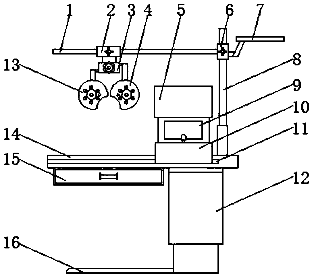
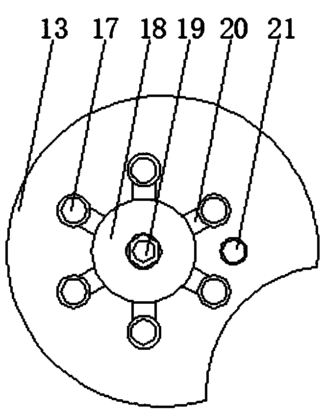
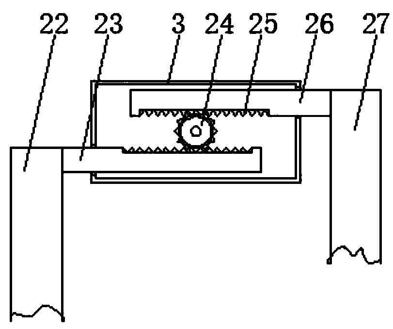
[0022] see Figure 1-5 , the present invention provides a technical solution: a computer refractometer for ophthalmic medical treatment, comprising a crossbar 1, a slider A2, an adjuster 3, a right shading sheet 4, an upper body 5, a slider B6, an outrigger 7, a vertical Rod 8, display screen 9, bottom body 10, slide rail 11, support leg 12, left shading sheet 13, workbench 14, storage drawer 15, bottom plate 16, lens slot 17, disc 18, pin shaft 19, connection...


PUM


Abstract

The invention discloses a computer optometry unit for ophthalmologic therapy. The bottom end of a support leg is fixedly connected with the upper surface of a bottom plate; a vertical bar is fixed toone end of the upper surface of a workbench; slider B is slidably connected to the vertical bar; the right end of slide plate B is fixedly connected with the upper end of connection bar B; a disc is rotationally connected with a left shade through a pin; six lens clamping channels are fixedly connected with the disc via connection sheets; the front and rear sides of the workbench are provided withslide rails respectively; a display screen is mounted in the front of a middle box; the bottom end of the base is fixedly connected with the upper surface of a bottom box; a screw is arranged in thebase; a cotton pad is fixed to the upper end of the frame. The lens clamping channels are fitted to the disc of the shades, lenses having different powers can be placed and can be switched just by rotating the disc, and a lens suitable for a patient can be found more accurately.

Description

technical field [0001] The invention relates to an optometry instrument, in particular to a computerized optometry instrument for ophthalmic medical treatment. Background technique [0002] With the rapid development of my country's economy and science and technology since the reform and opening up, my country's science and technology and economy have made great progress, especially the development of my country's science and technology has greatly promoted the development of my country's electronic products, electronic products such as computers, TVs and mobile phones It has been fully popularized, but although these electronic products enrich people's daily life, they also endanger people's eye health. These patients need to wear glasses. Generally, they need to use optometry equipment to measure the eye power before wearing glasses, but the current optometry The function of the equipment is relatively simple, and the adjustment of the current placement frame is relatively c...

Claims


Application Information

Patent Timeline
Patent Type & Authority Applications(China)
IPC IPC(8): A61B3/103
CPCA61B3/0075A61B3/103
Inventor 梁英辉
Owner 芜湖市奥尔特光电科技有限公司
Learn More