Radiotherapy positioning device for oncology department

A positioning device and tumor technology, applied in the field of medical devices, can solve problems such as unfavorable patient treatment, patient comfort discount, and uncontrollable patient temperature, so as to eliminate lesions in other locations, reduce work intensity, and reduce the difficulty of treatment. Effect

Inactive Publication Date: 2018-11-06
河南明珍方医药科技有限公司
View PDF0 Cites 3 Cited by
  • Summary
  • Abstract
  • Description
  • Claims
  • Application Information

AI Technical Summary

Problems solved by technology

[0002] At present, when radiotherapy is performed on tumor patients, the patient is mostly lying on the radiotherapy bed, and the radiotherapy apparatus is adjusted to perform radiotherapy on the diseased part. However, the existing radiotherapy apparatus is inconvenient to move around the bed board, and can only slide on both sides of the bed board. Rotating around the bed board at 360 degrees, there is a dead angle for treatment; the existing therapeutic equipment cannot be adjusted in height and length, it is difficult to target the diseased part for precise treatment, and it is easy to irradiate other parts and cause lesions in other parts; the radiotherapy process requires the patient to Keep a fixed lying position so as not to affect the treatment effect, but the existing head fixation device is not flexible enough and the operation is cumbersome, and the patient's limbs cannot be fixed as needed, and the patient's unconscious body shaking often brings treatment difficulties to the medical staff. It is also not conducive to the treatment of patients, and patients are prone to vomiting reactions during radiation therapy. Most vomiting behaviors will bring a lot of trouble to medical staff, and the patient's body temperature cannot be controlled during radiation therapy. Compromises patient comfort during radiation therapy

Method used


Image

  • Radiotherapy positioning device for oncology department
  • Radiotherapy positioning device for oncology department
  • Radiotherapy positioning device for oncology department

Examples


Embodiment Construction

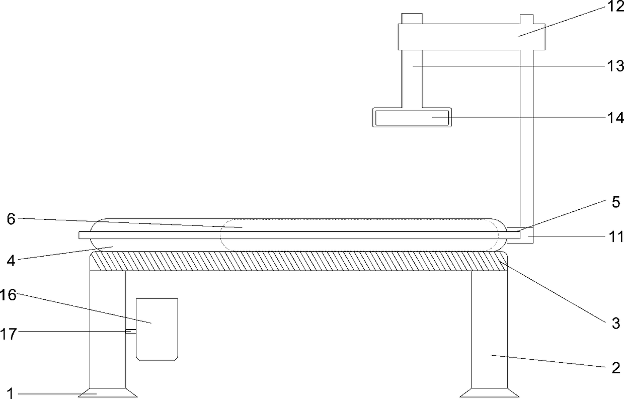
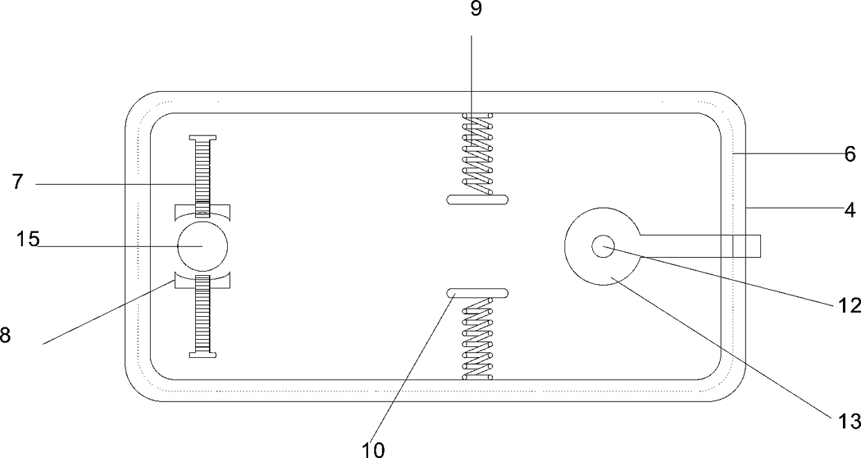
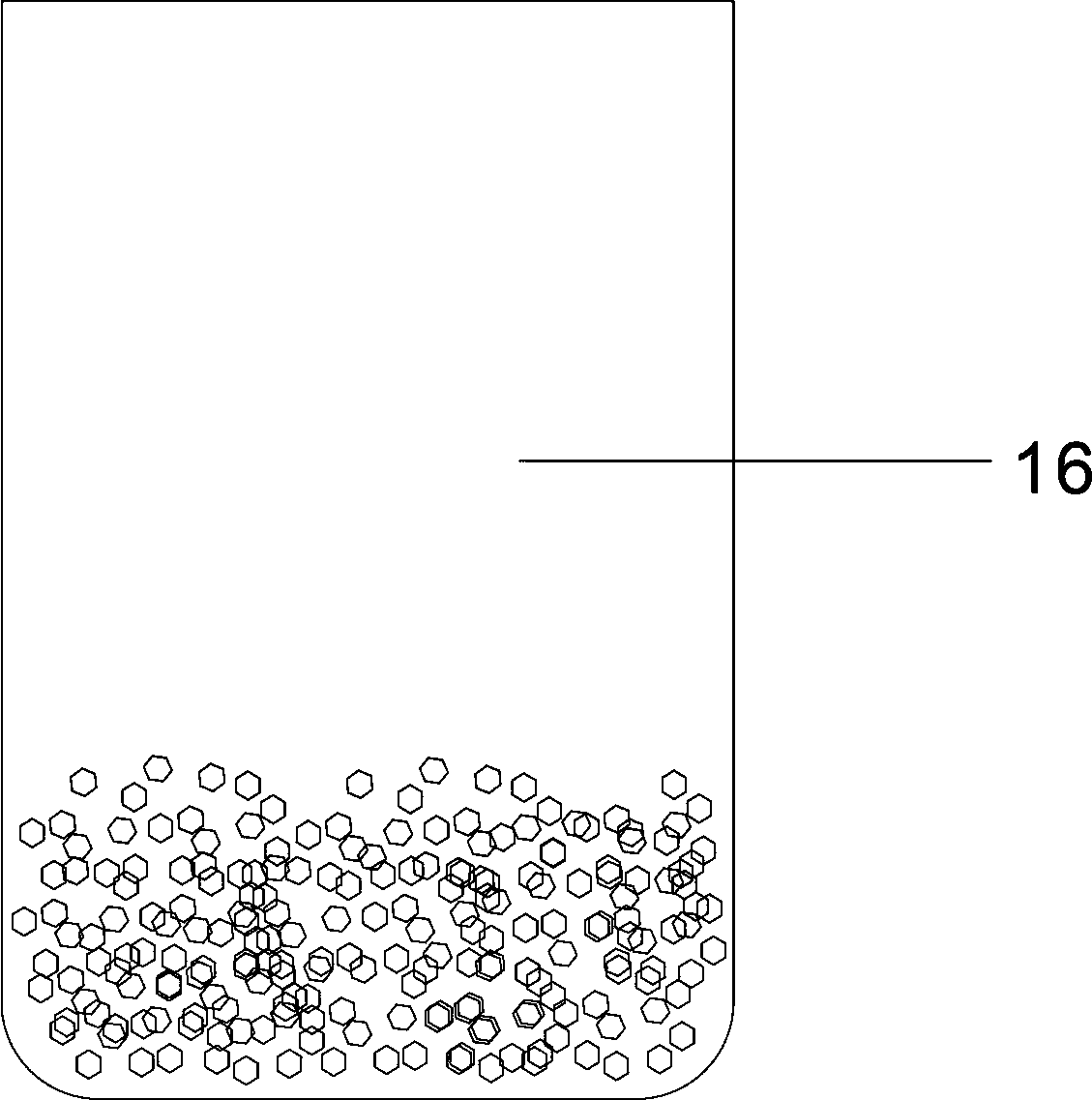
[0019] The present invention will be further described below in conjunction with specific embodiments, wherein, the accompanying drawings are only for exemplary illustrations, and what is shown is only a schematic diagram, rather than a physical map, and cannot be understood as a limitation to this patent. In order to better illustrate the present invention Specific embodiments, some parts in the drawings will be omitted, enlarged or reduced, and do not represent the size of the actual product. For those skilled in the art, it is understandable that some known structures and their descriptions in the drawings may be omitted. Based on The specific implementation modes in the present invention and all other specific implementation modes obtained by persons of ordinary skill in the art without making creative efforts all belong to the protection scope of the present invention.

[0020] see Figure 1-Figure 3 , the present invention provides a technical solution: a radiotherapy po...


PUM


Abstract

The invention discloses a radiotherapy positioning device for an oncology department. The radiotherapy positioning device comprises a trapezoidal positioning plate, wherein the top of the trapezoidalpositioning plate is fixedly connected with a support frame by welding; the top of the support frame is fixedly connected with a bearing plate by threads; the top of the bearing plate is fixedly connected to a central operation panel by springs; an electric heating blanket is disposed in the central operation panel; the top of the central operation panel is fixedly connected with symmetric stopping slide rails by nail joint; the tops of the stopping slide rails are connected with a headrest by stopping bolts; the top of the central operation panel is fixedly connected with an elastic frame bynail joint; the elastic frame is fixedly connected with a lumbar support pillow by nail joint; and the outer side of the central operation panel is provided with a round of guide rail by riveting. Theguide rail and a rotating shaft enable a radiotherapy apparatus to rotate around the central operation panel, thereby achieving precise positioning and greatly enhancing a therapeutic effect. Therefore, the radiotherapy positioning device for the oncology department has a broad application market.

Description

technical field [0001] The invention relates to the technical field of medical devices, in particular to a radiotherapy positioning device for oncology. Background technique [0002] At present, when radiotherapy is performed on tumor patients, the patient is mostly lying on the radiotherapy bed, and the radiotherapy apparatus is adjusted to perform radiotherapy on the diseased part. However, the existing radiotherapy apparatus is inconvenient to move around the bed board, and can only slide on both sides of the bed board. Rotating around the bed board at 360 degrees, there is a dead angle for treatment; the existing therapeutic equipment cannot be adjusted in height and length, it is difficult to target the diseased part for precise treatment, and it is easy to irradiate other parts and cause lesions in other parts; the radiotherapy process requires the patient to Keep a fixed lying position so as not to affect the treatment effect, but the existing head fixation device is ...

Claims


Application Information

Patent Timeline
Patent Type & Authority Applications(China)
IPC IPC(8): A61N5/10
CPCA61N5/10A61N2005/1097
Inventor 司会娟
Owner 河南明珍方医药科技有限公司
Why Eureka
Try Eureka