
Iron sheet slicing machine allowing automatic maintenance

A health maintenance and slicer technology, which is applied in the direction of manufacturing tools, metal processing, metal processing equipment, etc., can solve the problems of easy wear of the cutter, incomplete cutting, and impact, so as to improve processing efficiency, ensure accuracy, The effect of the precise slice effect

Inactive Publication Date: 2018-11-06
DONGGUAN UNIV OF TECH
View PDF0 Cites 2 Cited by
  • Summary
  • Abstract
  • Description
  • Claims
  • Application Information

AI Technical Summary

Problems solved by technology

[0003] Most of the existing slicing machines are relatively simple. The lifting cylinder is used to control the lowering of the cutter to realize the slicing of the iron sheet. However, during the slicing process, the cutter is prone to wear and tear. In order to ensure that the iron sheet will not be bent during slicing, when slicing, The blade is in hard contact with the bottom of the conveying tank, that is, the lowering height of the cutter is just enough to cut off the iron sheet. Once the cutter is worn, the material will be incompletely cut, which will affect the processing. Therefore, it is urgent to design a A device that can automatically maintain the health of the cutter to improve the efficiency of processing

Method used


Image

  • Iron sheet slicing machine allowing automatic maintenance
  • Iron sheet slicing machine allowing automatic maintenance
  • Iron sheet slicing machine allowing automatic maintenance

Examples


Embodiment Construction

[0029] In order to enable those skilled in the art to better understand the technical solution of the present invention, the present invention will be described in detail below in conjunction with the accompanying drawings. The description in this part is only exemplary and explanatory, and should not have any limiting effect on the protection scope of the present invention. .

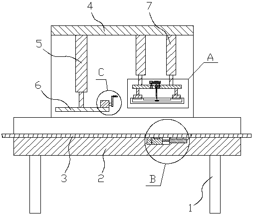
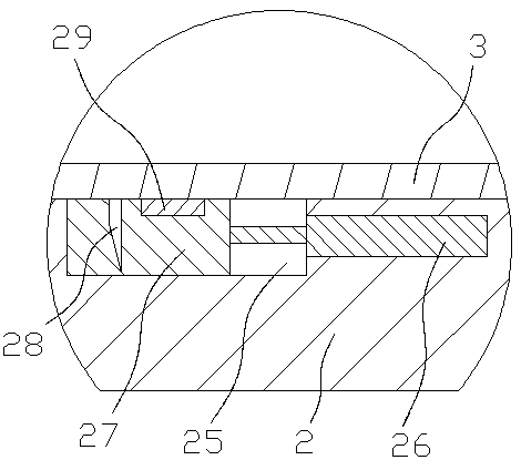
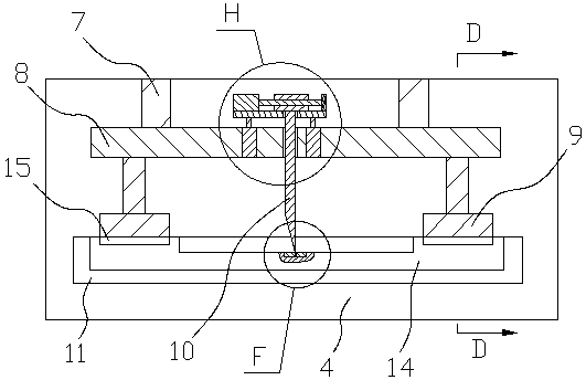
[0030] Such as Figure 1-Figure 8 As shown, the specific structure of the present invention is: a sheet metal slicer capable of automatic health maintenance, comprising a frame 1, the frame 1 is provided with a conveying trough seat 2 for conveying the sheet metal 3, and the conveying trough 2 is provided with a processing frame 4, the processing frame 4 is provided with a cutting cylinder 7, and the cutting lifting seat 8 is arranged below the cutting cylinder 7, and a cutting knife 10 is installed on the cutting lifting seat 8. The conveying trough seat 2 is provided with a left-right conversion gro...


PUM


Abstract

The invention relates to an iron sheet slicing machine allowing automatic maintenance. The iron sheet slicing machine comprises a machine frame, a conveying groove seat and a processing frame, a cutting-off air cylinder is arranged on the machining frame, a cutting-off lifting seat is arranged below the cutting-off air cylinder, a cutter is installed on the cutting-off lifting seat, the conveyinggroove seat is positioned below the cutter and is provided with a conversion groove which is provided with a left-and-right direction, a conversion movable block which is flush with the conveying groove seat is arranged in the conversion groove, the conversion movable block is connected with a conversion air cylinder in the left-right direction in the conveying groove base, the left part of the conversion movable block is provided with a grinding groove matched with the cutter, a cutter scribing inductor is embedded into the right part of the conversion movable block, the cutter scribing inductor is a pressure sensor capable of generating a whole pressure sensing signal and a local pressure induction signal. The movable conversion movable block is arranged at the position, located below the cutter, of the conveying groove, a cutting knife scribing inductor and a grinding groove are arranged on the conversion movable block, the grinding and repairing of the cutter can be realized through the grinding groove, the health maintenance of equipment is realized, and the processing efficiency is improved.

Description

technical field [0001] The invention relates to the field of equipment health maintenance, in particular to an iron slicer capable of automatic health maintenance. Background technique [0002] Iron sheet is a commonly used raw material for mechanical processing. In some applications, it needs to be sliced, and most of the slices are mechanically sliced. [0003] Most of the existing slicing machines are relatively simple. The lifting cylinder is used to control the lowering of the cutter to realize the slicing of the iron sheet. However, during the slicing process, the cutter is prone to wear and tear. In order to ensure that the iron sheet will not be bent during slicing, when slicing, The blade is in hard contact with the bottom of the conveying tank, that is, the lowering height of the cutter is just enough to cut off the iron sheet. Once the cutter is worn, the material will be incompletely cut, which will affect the processing. Therefore, it is urgent to design a A de...

Claims


Application Information

Patent Timeline
IPC IPC(8): B21D1/00B21D28/02B21C51/00
CPCB21D1/00B21C51/00B21D28/002B21D28/02
Inventor 李川
Owner DONGGUAN UNIV OF TECH
Learn More