Supercharge Your Innovation With Domain-Expert AI Agents!

Adjustable bearing clamp

An adjustable and fixture technology, applied in the field of bearing fixtures, can solve the problems of inseparability, single application, inconvenience to carry, etc., to achieve the effect of easy disassembly and assembly, various types of use, and easy to use and use.

Inactive Publication Date: 2018-11-06
ANHUI MGN BEARING
View PDF0 Cites 2 Cited by
  • Summary
  • Abstract
  • Description
  • Claims
  • Application Information

AI Technical Summary

Problems solved by technology

[0003] Although the existing bearing fixture can fix the bearing for processing, but the structure is relatively simple, it can only fix the bearing at an angle, the application is single, and it is not easy to carry.

Method used


Image

  • Adjustable bearing clamp
  • Adjustable bearing clamp
  • Adjustable bearing clamp

Examples


Embodiment 1

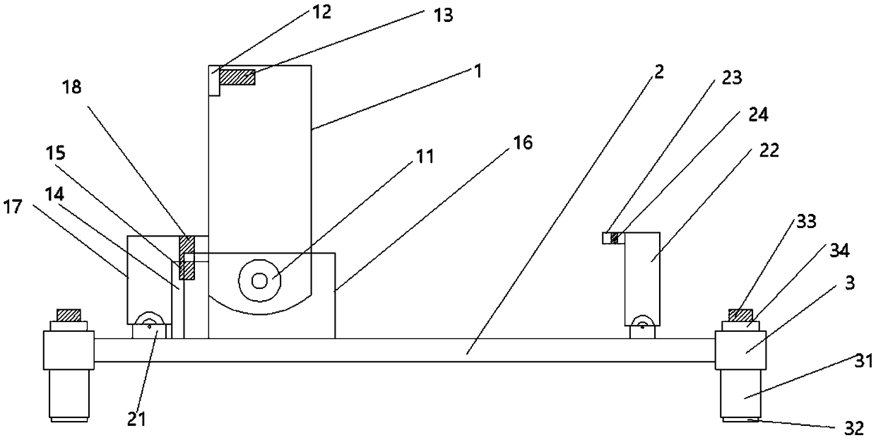
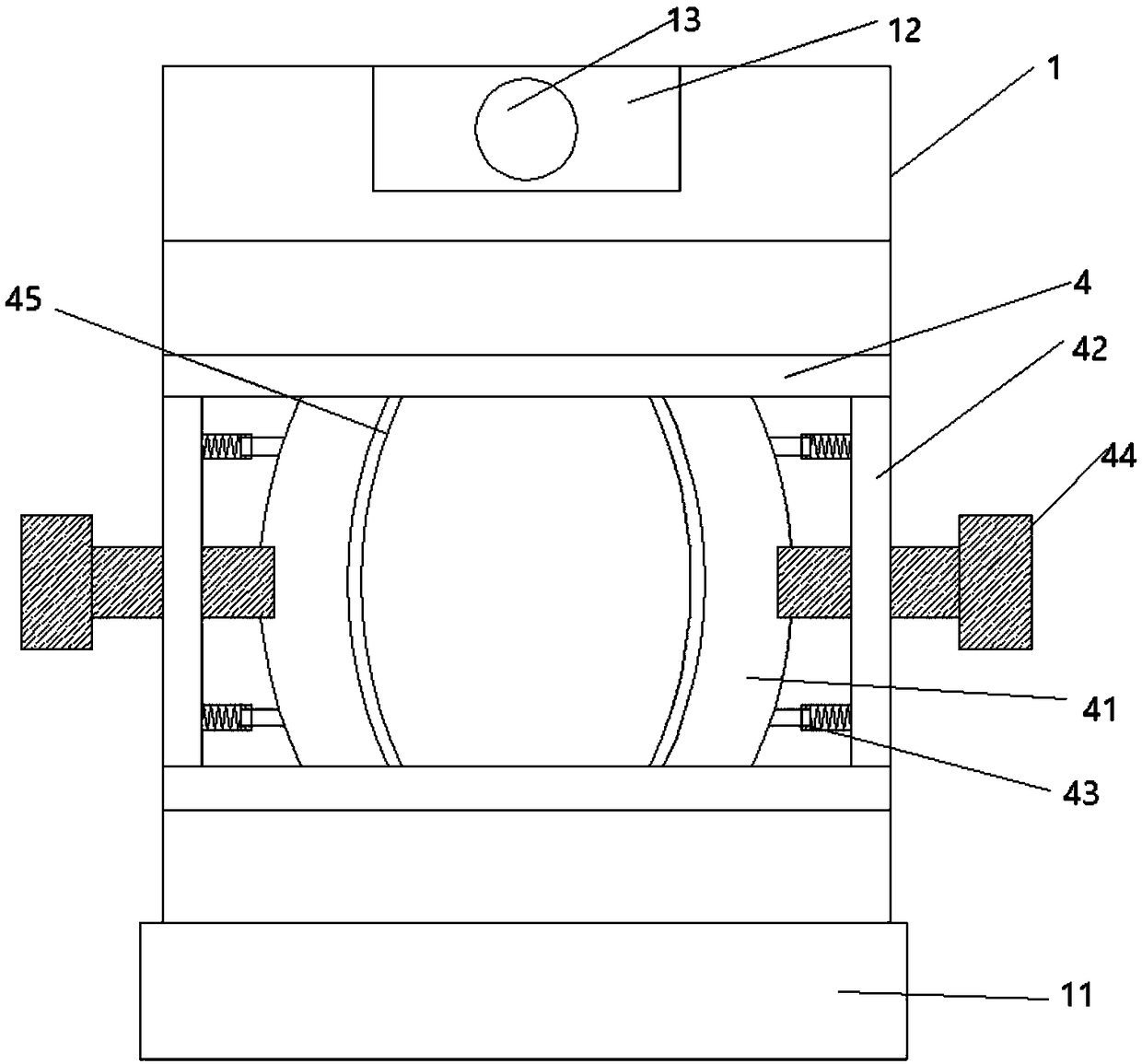
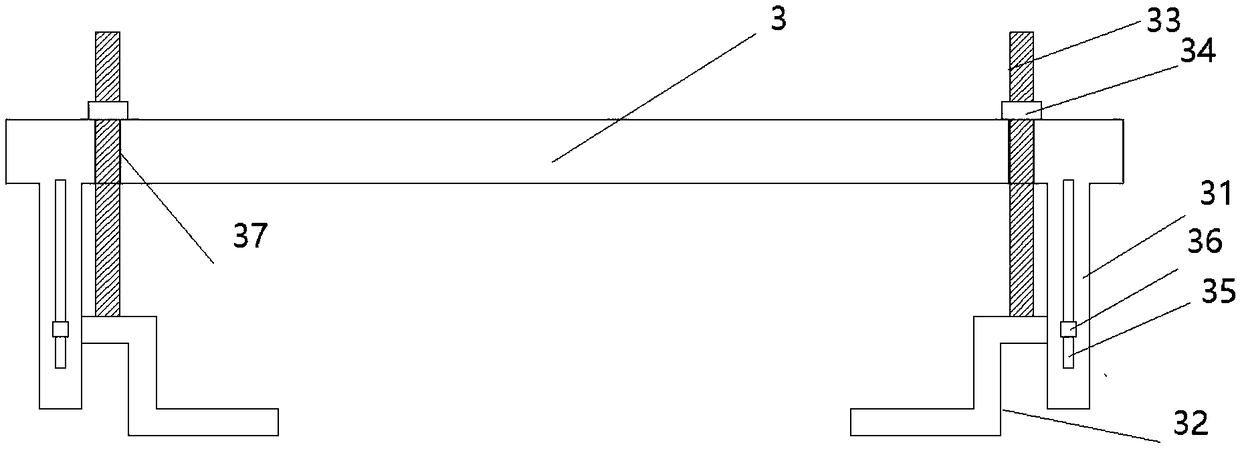
[0016] like Figure 1~3 As shown, an adjustable bearing fixture includes: a fixture module, a base 2, and an underframe, and the fixture module includes: a fixture shell 1 and a fixture block 14, and the fixture shell 1 is fixedly connected to the fixture block 14, and the fixture block 14 is located on the left side of the fixture shell 1, the upper end of the fixture shell 1 is provided with a fixture shell limit groove 12, and the fixture shell limit groove 12 is provided with a limit hole 13, and the lower end of the fixture shell 1 is provided with a rotating block 11, and the fixture shell The upper and lower ends of the middle of 1 are provided with sliding rods 4, the middle of the two sliding rods 4 is provided with a sliding limit plate 41, and the sliding limit plate 41 is provided with a sliding limit groove 45, and the two sides of the middle of the clamp shell 1 are provided with clamp shells to connect Block 42, the sliding limit plate 41 is connected with the c...

Embodiment 2

[0018] like Figure 1~3 As shown, an adjustable bearing fixture includes: a fixture module, a base 2, and an underframe, and the fixture module includes: a fixture shell 1 and a fixture block 14, and the fixture shell 1 is fixedly connected to the fixture block 14, and the fixture block 14 is located on the left side of the fixture shell 1, the upper end of the fixture shell 1 is provided with a fixture shell limit groove 12, and the fixture shell limit groove 12 is provided with a limit hole 13, and the lower end of the fixture shell 1 is provided with a rotating block 11, and the fixture shell The upper and lower ends of the middle of 1 are provided with sliding rods 4, the middle of the two sliding rods 4 is provided with a sliding limit plate 41, and the sliding limit plate 41 is provided with a sliding limit groove 45, and the two sides of the middle of the clamp shell 1 are provided with clamp shells to connect Block 42, the sliding limit plate 41 is connected with the c...

Embodiment 3

[0021] like Figure 1~3 As shown, an adjustable bearing fixture includes: a fixture module, a base 2, and an underframe, and the fixture module includes: a fixture shell 1 and a fixture block 14, and the fixture shell 1 is fixedly connected to the fixture block 14, and the fixture block 14 is located on the left side of the fixture shell 1, the upper end of the fixture shell 1 is provided with a fixture shell limit groove 12, and the fixture shell limit groove 12 is provided with a limit hole 13, and the lower end of the fixture shell 1 is provided with a rotating block 11, and the fixture shell The upper and lower ends of the middle of 1 are provided with sliding rods 4, the middle of the two sliding rods 4 is provided with a sliding limit plate 41, and the sliding limit plate 41 is provided with a sliding limit groove 45, and the two sides of the middle of the clamp shell 1 are provided with clamp shells to connect Block 42, the sliding limit plate 41 is connected with the c...


PUM


Abstract

The invention discloses an adjustable bearing clamp. The adjustable bearing clamp comprises a clamp module, a base and a bottom frame; a clamp shell is fixedly connected to a clamp block, a clamp shell limiting groove is formed in the upper end of the clamp shell, a limiting hole is formed in the clamp shell limiting groove, a rotating block is arranged at the lower end of the clamp shell, slidingrods are arranged at the upper end and the lower end of the middle of the clamp shell, and a sliding limiting plate is arranged in the middle of the two sliding rods; a sliding limiting groove is formed in the sliding limiting plate, clamp shell connecting blocks are arranged on the two sides of the middle of the clamp shell, the rotating block is connected to a rotating groove in a rotating mode, and the lower end of the rotating groove is connected to the base; and small rotating grooves are formed in the upper end of the base, the small rotating groove in the left side is rotationally connected to a vertical plate, a vertical plate limiting hole is formed in the upper end of the vertical plate, the small rotating groove at the right side is connected to a transverse plate in a rotatingmode, a transverse plate limiting hole is formed in the transverse plate, and base frames are arranged on the two sides of the base. According to the adjustable bearing clamp, the clamp is selected to be vertically placed or horizontally placed according to the situation, the using mode is changeable, the bottom frame and most of the machine are connected to a workbench, so that the use type of the clamp is more diversified, and the clamp is easy to disassemble and assemble and convenient to use by hands.

Description

technical field [0001] The invention relates to the technical field of industrial production, in particular to an adjustable bearing clamp. Background technique [0002] Bearing is a part of mechanical equipment. It is an important part to support the mechanical rotating body, reduce the friction coefficient during its movement, and ensure its rotation accuracy. The bearing fixture is to fix the bearing for processing and processing. A fixture that is an important tool in bearing machining activities. [0003] Although the existing bearing fixture can fix the bearing for processing, the structure is relatively simple, and the bearing can only be fixed at an angle. The application is single, and it is not easy to carry. Contents of the invention [0004] The technical problem solved by the present invention is to provide an adjustable bearing clamp to solve the problems raised in the above-mentioned background technology. [0005] The technical problem solved by the prese...

Claims


Application Information

Patent Timeline
Patent Type & Authority Applications(China)
IPC IPC(8): B23Q3/06
CPCB23Q3/06B23Q3/062
Inventor 张士校李兵王世强
Owner ANHUI MGN BEARING
Features
  • R&D
  • Intellectual Property
  • Life Sciences
  • Materials
  • Tech Scout
  • Unparalleled Data Quality
  • Higher Quality Content
  • 60% Fewer Hallucinations
Learn More