Processing equipment for metal blades

A technology for processing equipment and metal blades, which is applied in the field of automatic grinding equipment for metal blades, and can solve the problems of low processing accuracy and low processing efficiency

Active Publication Date: 2019-05-24
南通兴东叶片科技有限公司
View PDF6 Cites 0 Cited by
  • Summary
  • Abstract
  • Description
  • Claims
  • Application Information

AI Technical Summary

Problems solved by technology

The existing metal blade grinding is to fix the blade through the clamp and grind it through the yarn wheel. The arc processing is realized by adjusting the front and rear positions of the clamp, and the processing accuracy is low. In addition, the blade must be loaded and unloaded for each processing. , low processing efficiency

Method used


Image

  • Processing equipment for metal blades
  • Processing equipment for metal blades
  • Processing equipment for metal blades

Examples


Embodiment Construction

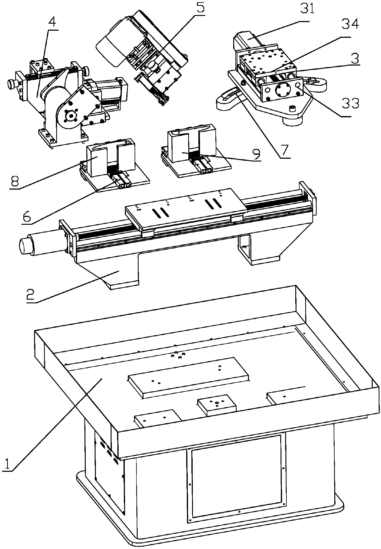
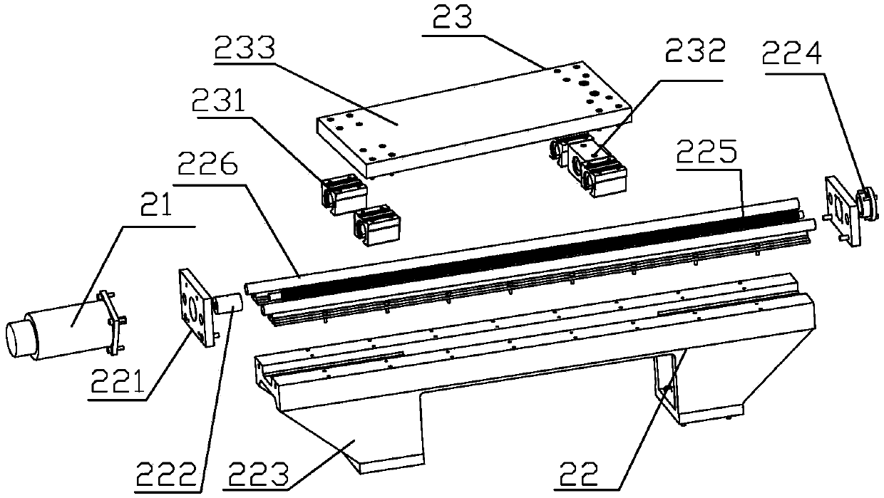
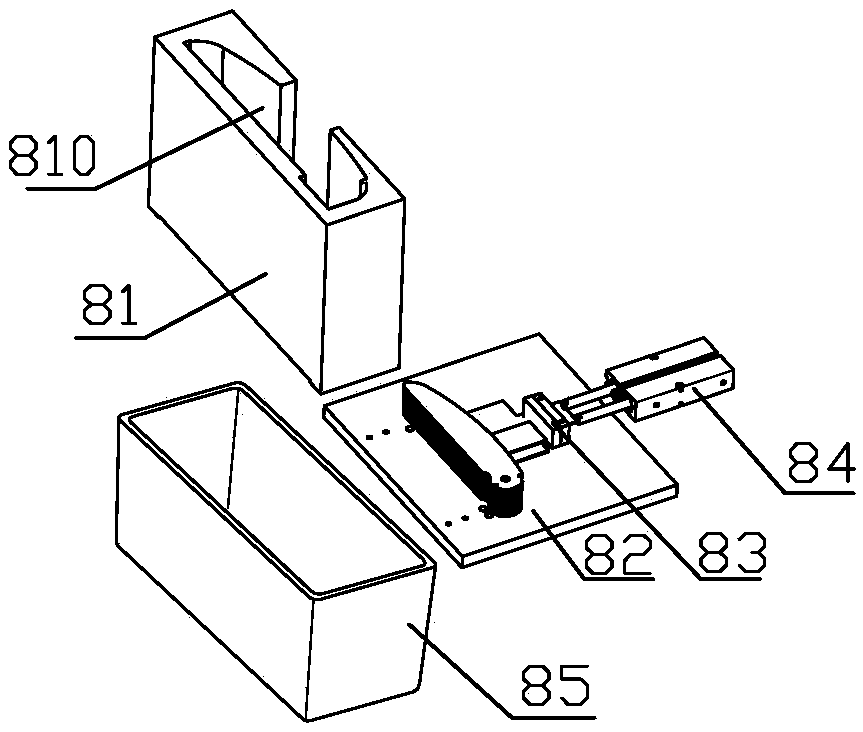
[0036] Combine below Figure 1-Figure 20 The present invention is further described.

[0037] Such as Figure 1-Figure 20 The metal blade processing equipment shown includes frame 1, X-axis lateral movement device 2, operating bottom plate device 7, Y-axis forward and backward movement device 3, spindle grinding wheel rotation device 4, grinding device 5, and blade clamping device and controller. The X-axis lateral moving device 2 and the operating base plate device 7 are fixed on the frame 1, the blade clamping device is installed on the X-axis lateral moving device 2; the Y-axis forward and backward moving device 3 is connected to the operating base plate device 7, and the main shaft grinding wheel The rotating device 4 and the grinding device 5 are installed on the Y-axis forward and backward moving device 3 . The controller is installed on the frame, and the controller controls the actions of the X-axis lateral movement device, the operation base plate device, the Y-axi...


PUM


Abstract

The invention relates to the field of intelligent mechanical equipment. Metal blade machining equipment comprises a rack, an X-axis transverse movement device and a blade clamping device; and the X-axis transverse movement device is fixed to the rack, and the blade clamping device is installed on the X-axis transverse movement device. The metal blade machining equipment has the advantage that themachining efficiency and the machining accuracy ate high.

Description

technical field [0001] The invention relates to the field of intelligent mechanical equipment, in particular to automatic grinding equipment for metal blades. Background technique [0002] Metal blades are used extensively, for example in ventilation settings. There are two main types of metal blades, one is straight at both ends, and the other is straight at one end and curved at the other end. The existing metal blade grinding is to fix the blade through the jig and grind it through the yarn wheel. The arc processing is realized by adjusting the front and rear positions of the jig, and the processing accuracy is low. In addition, the blade must be loaded and unloaded for each processing. , low processing efficiency. Contents of the invention [0003] The object of the present invention is to provide a metal blade processing equipment with high processing efficiency and processing precision. [0004] In order to achieve the above object, the present invention adopts th...

Claims


Application Information

Patent Timeline
Patent Type & Authority Patents(China)
IPC IPC(8): B24B19/14B24B41/06
CPCB24B19/14B24B41/06
Inventor 柯文光
Owner 南通兴东叶片科技有限公司
Why Eureka
Try Eureka