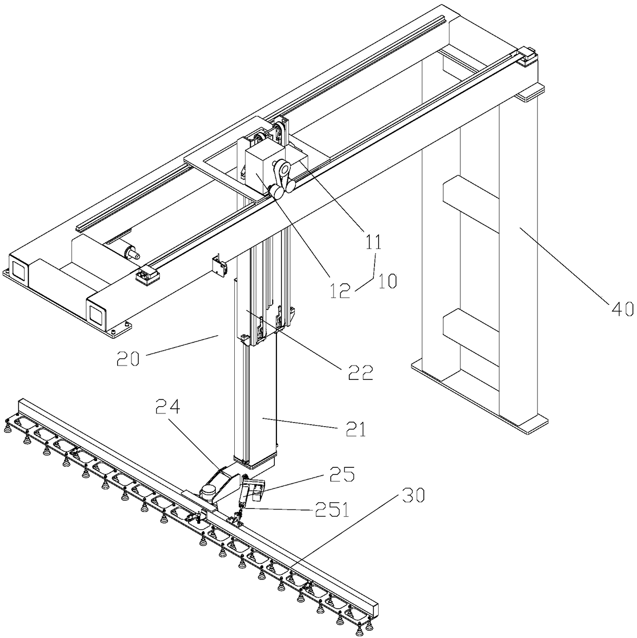
Material transferring mechanism

A material and object technology, applied in the field of material transfer mechanism, can solve problems such as low degree of automation, achieve fast transfer, and solve the effect of low degree of automation

Pending Publication Date: 2018-11-06
MESNAC
View PDF9 Cites 4 Cited by
  • Summary
  • Abstract
  • Description
  • Claims
  • Application Information

AI Technical Summary

Problems solved by technology

[0004] The main purpose of the present invention is to provide a material transfer mechanism to solve the problem of low automation of the material transfer mechanism in the prior art

Method used


Image

  • Material transferring mechanism
  • Material transferring mechanism
  • Material transferring mechanism

Examples


Embodiment Construction

[0029] It should be noted that the embodiments in the application and the features in the embodiments can be combined with each other if there is no conflict. Hereinafter, the present invention will be described in detail with reference to the drawings and in conjunction with the embodiments.

[0030] It should be pointed out that the following detailed descriptions are all illustrative and are intended to provide further explanations for the application. Unless otherwise indicated, all technical and scientific terms used herein have the same meaning as commonly understood by those of ordinary skill in the technical field to which this application belongs.

[0031] It should be noted that the terms used here are only for describing specific embodiments, and are not intended to limit the exemplary embodiments according to the present application. As used herein, unless the context clearly indicates otherwise, the singular form is also intended to include the plural form. In additio...


PUM


Abstract

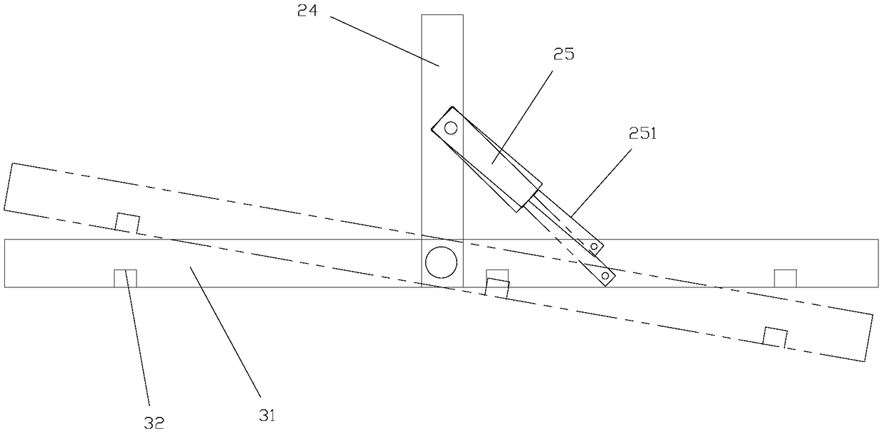
The invention provides a material transferring mechanism. The material transferring mechanism comprises a driving assembly, a connecting assembly and a grabbing part, wherein the driving assembly is in driving connection with the connecting assembly, the grabbing part is connected with the connecting assembly, the grabbing part is used for grabbing an object, and the grabbing part can be adjustably arranged relative to the connecting assembly in position. According to the material transferring mechanism, the problem that the automation degree of a material transferring mechanism in the prior art is low is solved.

Description

Technical field [0001] The invention relates to the field of material transfer machinery, in particular to a material transfer mechanism. Background technique [0002] The all-steel tread is usually stored on the page plate of the 100-page car. When the forming machine makes the tire, the tread needs to be taken out and placed on the transfer template. Since the height of each layer of the tread louver and the placement position of the tread on the page plate are uncertain, the tread should be straightened first when the automatic tire removal is carried out, and the height direction should be realized in the process of tread transmission. Precise control of movement. [0003] In the prior art, the tread is manually taken out from the hundred-page cart and placed on the conveying template. However, the manual handling efficiency is low and labor intensity is high, which is not conducive to the realization of the automation of the all-steel forming machine. Summary of the inventio...

Claims


Application Information

Patent Timeline
Patent Type & Authority Applications(China)
IPC IPC(8): B65G47/91
CPCB65G47/901
Inventor 武守涛彭地金贾海玲周福德张立康付赵磊
Owner MESNAC
Why Eureka
Try Eureka