Beating device of toilet paper machine

A technology for toilet paper and equipment, applied in the field of beating equipment, can solve the problems of reducing stirring resistance, shortening beating time, and reducing energy consumption of a beating machine, and achieves the effects of simple structure, convenient operation and uniform beating

Inactive Publication Date: 2018-11-06
郭文英
View PDF8 Cites 5 Cited by
  • Summary
  • Abstract
  • Description
  • Claims
  • Application Information

AI Technical Summary

Problems solved by technology

The beating equipment of the toilet paper machine has not less than three sets of hubs, and the three sets of hubs are arranged at intervals on the surface of the shaft. The three sets of hubs are equipped with paddles, and the paddles are equipped with auxiliary paddles, which can shorten the beating time. Time, improve beating efficiency, by setting diversion grooves on the blade and auxiliary blade, the size of the blade gradually decreases from the blade root to the blade end, which can reduce the stirring resistance, thereby reducing the energy consumption of the beater, through There is a reinforcing plate between the hub and the paddle to ensure the firmness of the paddle, but the beating device is not uniform enough to meet the needs of customers

Method used


Image

  • Beating device of toilet paper machine
  • Beating device of toilet paper machine
  • Beating device of toilet paper machine

Examples


Embodiment

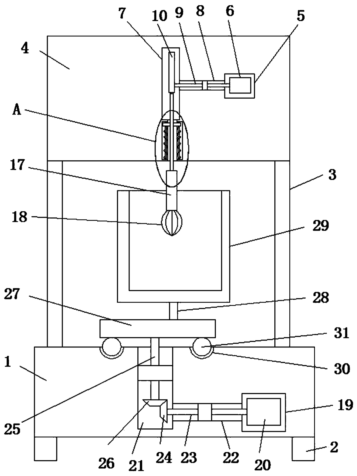
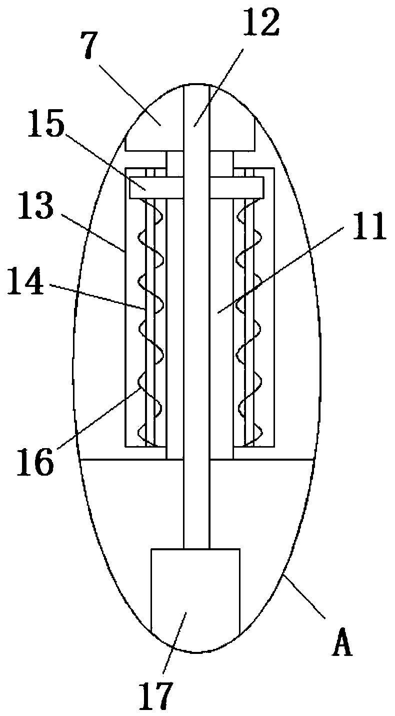
[0025] refer to Figure 1-5 In this embodiment, a beating equipment for a toilet paper machine is proposed, which includes a base 1, a plurality of legs 2 are fixedly installed on the bottom side of the base 1, and a plurality of pillars 3 are fixedly installed on the top side of the base 1, and one of the pillars 3 The side is fixedly installed with the same mount 4, the mount 4 is provided with a first motor chamber 5, the first motor chamber 5 is fixedly installed with a first motor 6, the mount 4 is provided with a cavity 7, and the first motor chamber 5 A communication hole 8 is provided on the inner wall near the cavity 7, the communication hole 8 communicates with the cavity 7, a rotating shaft 9 is installed in the communication hole 8, and the end of the rotating shaft 9 near the first motor chamber 5 extends to the first The motor cavity 5 is fixedly connected with the output shaft of the first motor 6, and the other end of the rotating shaft 9 extends into the cavit...


PUM


Abstract

The invention discloses a beating device of a toilet paper machine. The beating device comprises a base, a plurality of supporting legs are fixedly installed on the bottom side of the base, the top side of the base is fixedly provided with a plurality of supporting columns, and one sides of the supporting columns are fixedly provided with a same installation base. A first motor cavity is formed inthe installation base, a first motor is fixedly installed in the first motor cavity, a cavity is formed in the installation base, a communication hole is formed in the inner wall on the side, close to the cavity, of the first motor cavity, and the communication hole is communicated with the cavity. A rotary shaft is rotationally installed in the communication hole, the end, close to the first motor cavity, of the rotary shaft extends into the first motor cavity and is fixedly connected with an output shaft of the first motor, and the other end of the rotary shaft extends into the cavity and is fixedly provided with a cam. By means of the beating device, a stirring barrel can be rotated, pulp in the stirring barrel can be uniformly shaken, while stirring is conducted, the stirring barrel can do reciprocating motion up and down, the pulp in the stirring barrel is stirred and beaten at different depths, beating is uniform, the structure is simple, and operation is simple.

Description

technical field [0001] The invention relates to the technical field of beating equipment, in particular to a beating equipment of a toilet paper machine. Background technique [0002] Toilet paper is mainly used for people's daily hygiene, and is one of the indispensable paper types for the people. There are many raw materials for making toilet paper, and natural and pollution-free raw materials such as cotton pulp, wood pulp, bamboo pulp, and grass pulp are commonly used. [0003] Patent No. 201620410432.4 discloses a toilet paper beating device, which includes a beating barrel, a support frame and a shaft. The beating barrel is arranged above the support frame, and above the beating barrel A feed channel is provided, and a filter device is arranged in the feed channel, and a discharge pipe is provided at the bottom of the beating barrel, and the discharge pipe is arranged in an L shape, and the discharge pipe runs through the inside of the support frame, and the discharge...

Claims


Application Information

Patent Timeline
Patent Type & Authority Applications(China)
IPC IPC(8): D21D1/02B01F9/12B01F29/83
CPCD21D1/02B01F29/83B01F2101/47
Inventor 郭文英
Owner 郭文英
Why Eureka
Try Eureka