
Multifunctional idle gear shaft device

A gear shaft, multi-functional technology, applied in the direction of lubricant conduit devices, engine components, machines/engines, etc., can solve the problems that the lubricating oil cannot be directly reached, affect the overall layout of the engine, increase the cost, etc., so as to facilitate the overall layout and structure. Simple, low-cost effects

Active Publication Date: 2018-11-06
GUANGXI YUCHAI MASCH CO LTD
View PDF8 Cites 0 Cited by
  • Summary
  • Abstract
  • Description
  • Claims
  • Application Information

AI Technical Summary

Problems solved by technology

The first oil passage 101 of the prior art can only supply the lubrication of the first idler gear shaft of the prior art, and the lubricating oil cannot directly reach the second oil passage 102 of the prior art from the first oil passage 101 of the prior art, and must be re-lubricated. Open a third oil passage 103 of the prior art to supply oil to the second oil passage 102 of the prior art, so that the second oil passage 102 of the prior art can supply oil to the second idler gear shaft of the prior art for lubrication
[0004] The defect of the existing technology is: the idler gear shaft can only be designed on the oil passage, and when the oil inlet of the idler paper wheel shaft cannot be arranged on the oil passage due to machining restrictions or gear layout restrictions, the idler gear shaft cannot guide oil for forced lubrication However, it is necessary to use external pipelines for oil extraction and lubrication, which not only increases the cost, but also affects the overall layout of the engine.

Method used


Image

  • Multifunctional idle gear shaft device
  • Multifunctional idle gear shaft device
  • Multifunctional idle gear shaft device

Examples


Embodiment Construction

[0018] The specific embodiments of the present invention will be described in detail below in conjunction with the accompanying drawings, but it should be understood that the protection scope of the present invention is not limited by the specific embodiments.

[0019] Unless expressly stated otherwise, throughout the specification and claims, the term "comprise" or variations thereof such as "includes" or "includes" and the like will be understood to include the stated elements or constituents, and not Other elements or other components are not excluded.

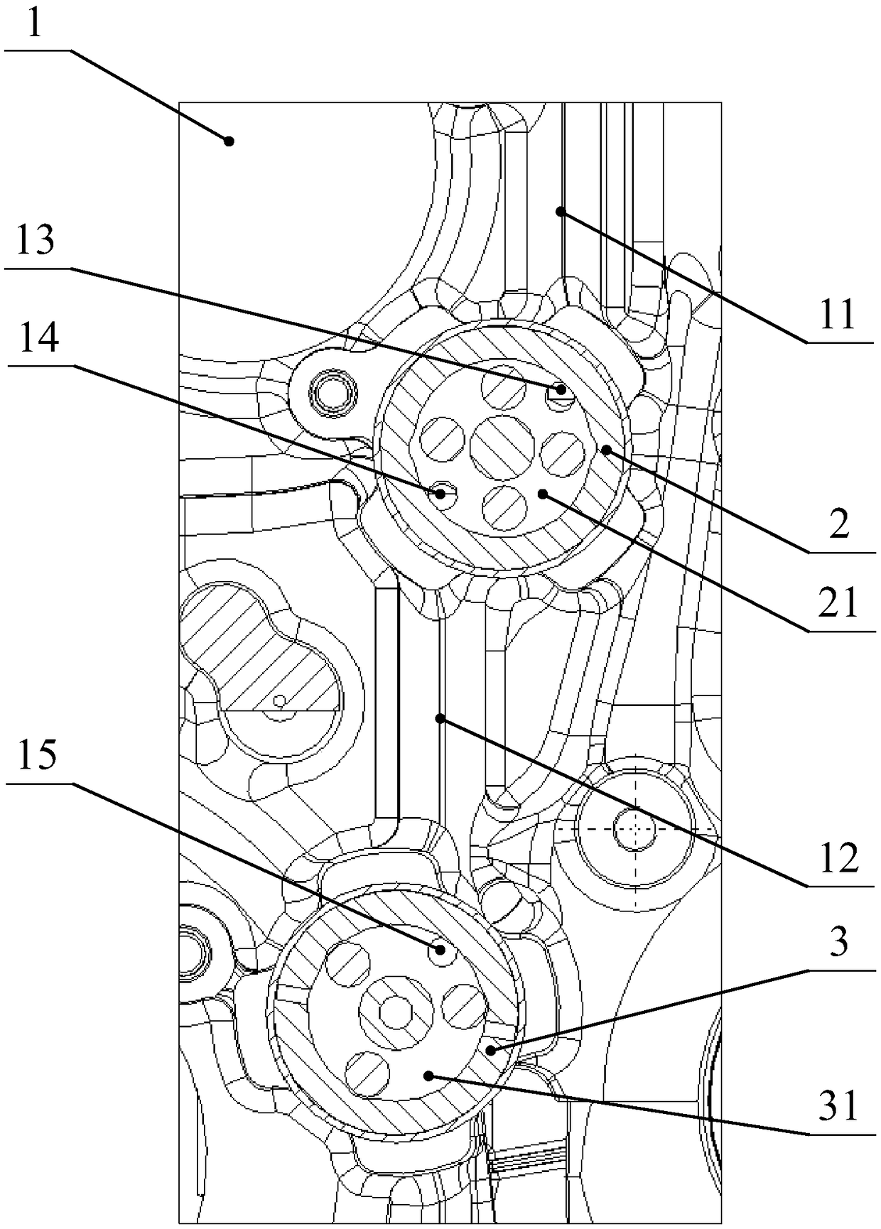
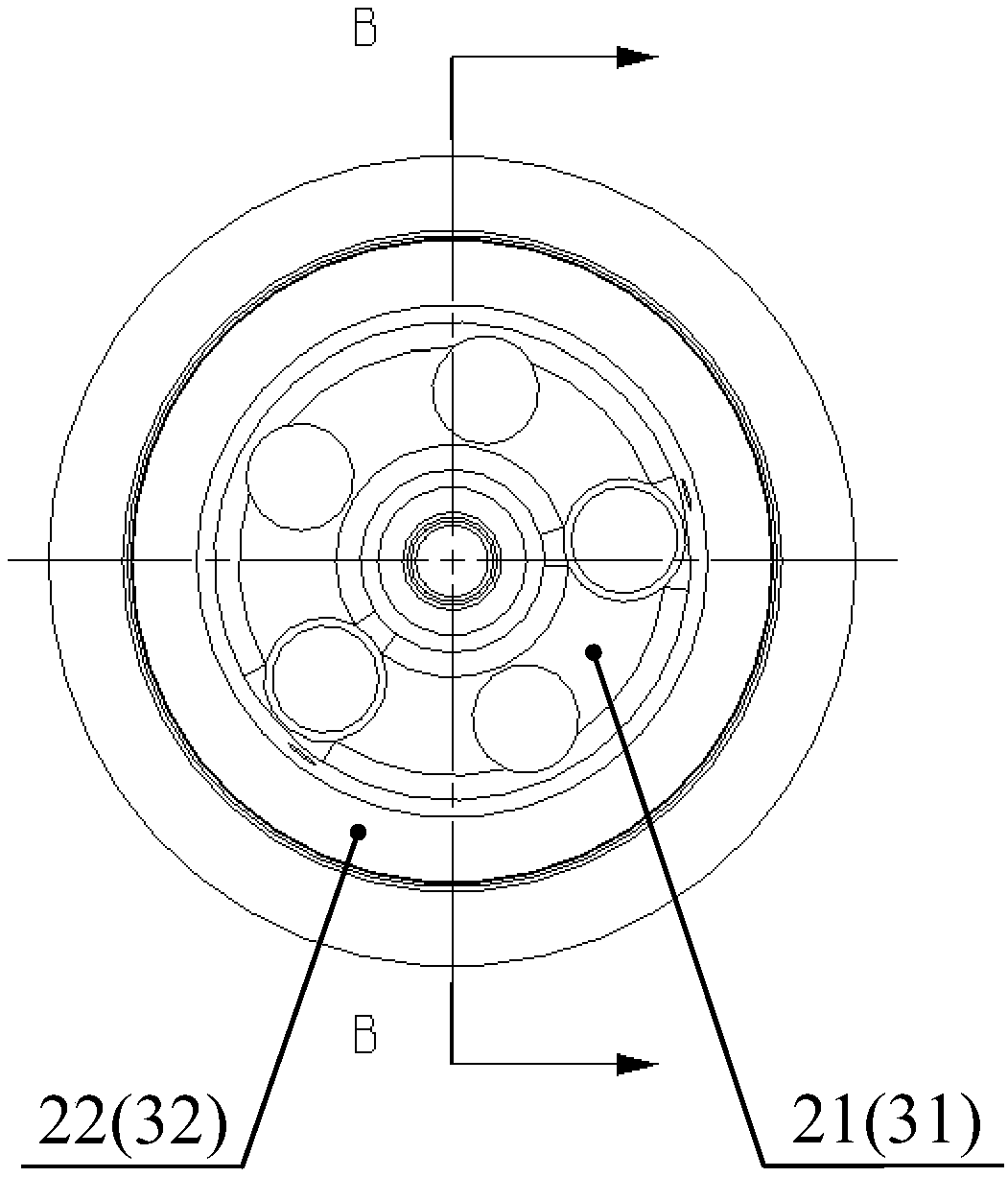
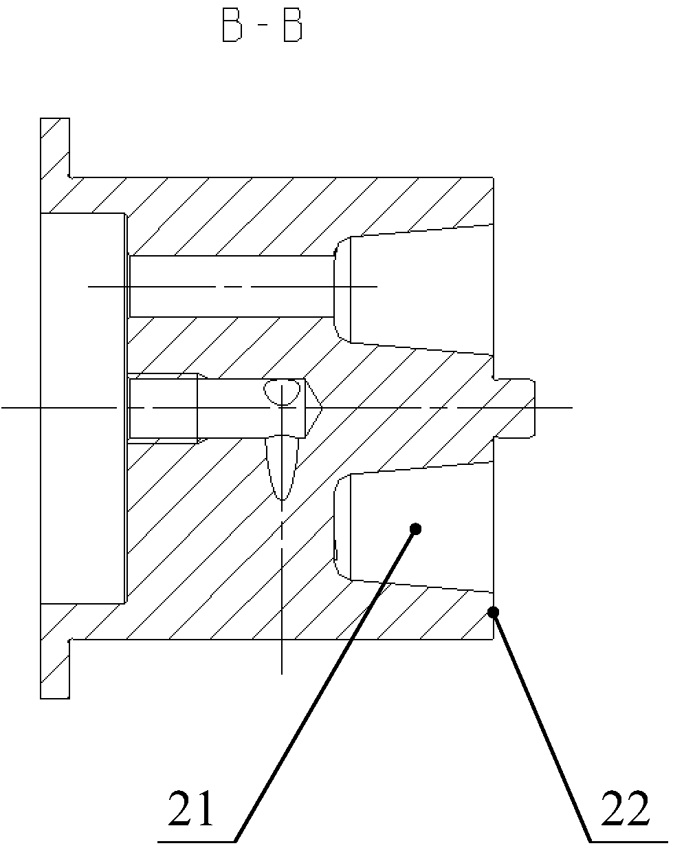
[0020] Such as Figure 1 to Figure 3 as shown, figure 1 is a layout diagram of a multifunctional idler gear shaft according to an embodiment of the present invention. figure 2 is a schematic front view of a multifunctional idler gear shaft according to an embodiment of the present invention. image 3 It is a BB direction sectional view of the multifunctional idler gear shaft according to one embodiment of the present i...


PUM


Abstract

The invention discloses a multifunctional idle gear shaft device. The multifunctional idle gear shaft device is arranged on the end surface of an air cylinder body, the multifunctional idle gear shaftdevice comprises a first oil way, a first oil distribution hole, a second oil distribution hole, a first idle gear shaft, a second oil way, a third oil distribution hole and a second idle gear shaft;the first oil way is vertically arranged on the upper part of the end surface of the air cylinder body, the first oil distribution hole is formed in the lower end of the first oil way, and communicates with the first oil way, the second oil distribution hole is formed in the end surface of the air cylinder body, and is located obliquely below the first oil distribution hole, the first idle gear shaft is arranged on the end surface of the air cylinder body, and covers the first oil distribution hole and the second oil distribution hole, the second oil way is vertically arranged in the middle of the end surface of the air cylinder body, the upper end of the second oil way communicates with the second oil distribution hole, the third oil distribution hole is formed in the lower end of the second oil way, and communicates with the second oil way, and the second idle gear shaft is arranged at the end surface of the air cylinder body, and covers the third oil distribution hole. According tothe multifunctional idle gear shaft device, forced lubrication of the idler gear shafts can be realized.

Description

technical field [0001] The invention relates to the field of internal combustion engines, in particular to a multifunctional idle gear shaft device capable of forced lubrication. Background technique [0002] The idler gear of the engine needs forced lubrication when the load is large, and splash and oil mist lubrication cannot meet the requirements. Generally, the idler gear shaft is designed on the oil passage, and the lubricating oil is introduced into the idler gear shaft through the machined oil hole. The disadvantage of this design is that the idler gear can only be designed on the oil hole. If the machining is difficult or the oil passage layout is difficult, the gear and the idler gear shaft can only be lubricated by an external oil pipe. At the same time, the traditional idler gear needs to open a platform at the oil hole, so that the lubricating oil can enter the gap between the idler gear shaft and the gear as soon as possible when the engine is started, so as to ...

Claims


Application Information

Patent Timeline
Patent Type & Authority Applications(China)
IPC IPC(8): F01M11/02F01M11/00F02F7/00
CPCF01M11/00F01M11/02F02F7/0065
Inventor 向本杰余锦海覃文王鹏程王志刚黎华文余晓强卢祥林田战胜张通
Owner GUANGXI YUCHAI MASCH CO LTD
Learn More