
Transmission case and retarder gear lubrication structure thereof

A lubricating structure and retarder technology, which is applied in the direction of gear lubrication/cooling, belt/chain/gear, transmission parts, etc., can solve the problems of low reliability and safety, reduced service life of retarder gears, and loss of gears. Problems such as insufficient lubrication are not enough to achieve the effect of simple and reasonable arrangement of lubricating oil circuit, ensuring normal operation and good lubricating effect

Pending Publication Date: 2019-04-09
SHANGHAI SUODA TRANSMISSION MACHINERY
View PDF0 Cites 0 Cited by
  • Summary
  • Abstract
  • Description
  • Claims
  • Application Information

AI Technical Summary

Problems solved by technology

[0003] At present, the ordinary splash lubrication method is still used for the lubrication of the transmission gear of the retarder. Although the structure of the splash lubrication method is relatively simple and the cost is low, its lubrication effect is affected by conditions such as the level of the oil level, the inclination of the truck, and the speed of the engine. Some parts of the gears are often not fully lubricated, which will not only reduce the service life of the retarder gears, but even damage the gears and cause the retarder to fail, so the reliability and safety are not high
In addition, some gearboxes adopt the method of arranging the oil pipe inside the casing to lubricate the retarder gear, but the arrangement of the oil pipe inside the casing is not conducive to the arrangement of other important mechanical components in the gearbox and the normal operation of the functions, which makes the early design of the gearbox become difficult and affect the overall reliability of the gearbox
[0004] Therefore how to solve problems such as insufficient lubrication of retarder gears and affecting the layout of gearbox components is a technical problem that those skilled in the art need to solve at present

Method used


Image

  • Transmission case and retarder gear lubrication structure thereof
  • Transmission case and retarder gear lubrication structure thereof
  • Transmission case and retarder gear lubrication structure thereof

Examples


Embodiment Construction

[0026] The core of the present invention is to provide a retarder gear lubricating structure of the gearbox, which realizes the forced lubrication of the retarder gear through the drainage of the external oil pipe. Parts interfere. Another core of the present invention is to provide a gearbox comprising the above retarder gear lubrication structure

[0027] In order to enable those skilled in the art to better understand the solution of the present invention, the present invention will be further described in detail below in conjunction with the accompanying drawings and specific embodiments.

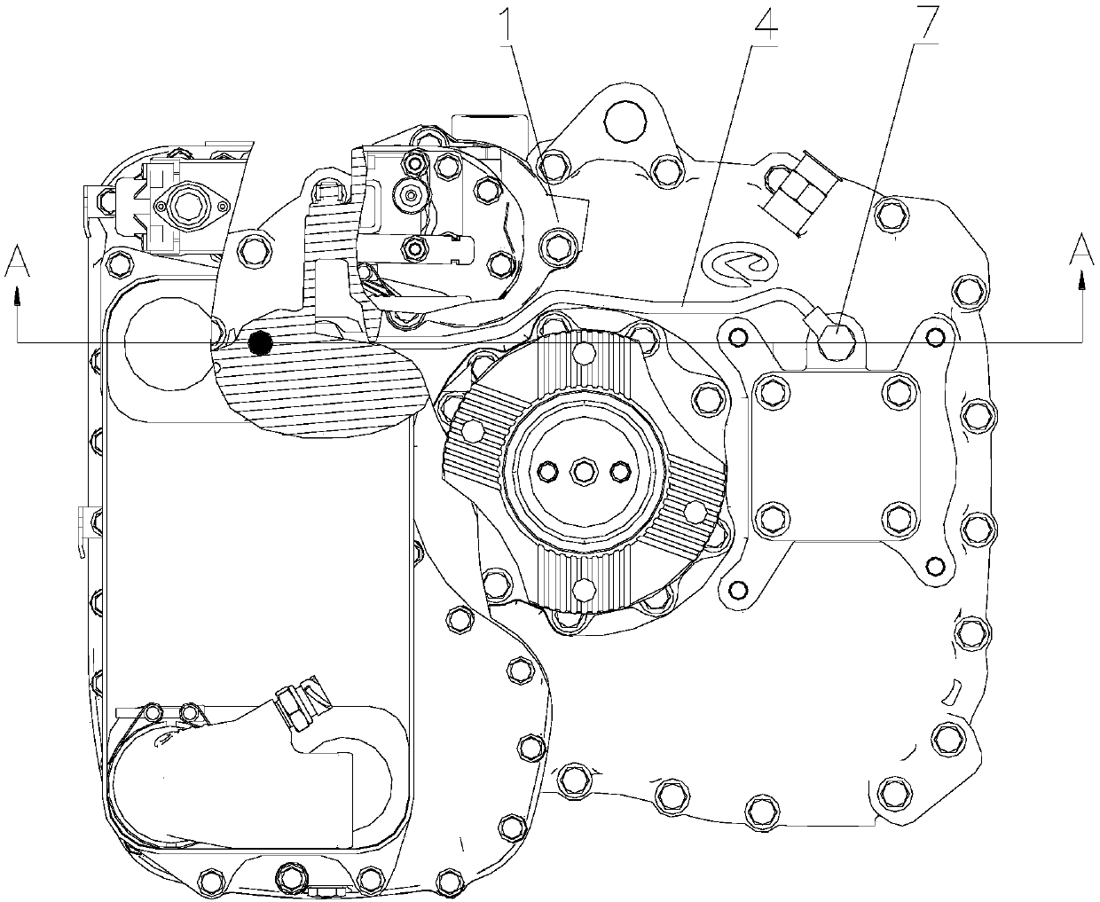
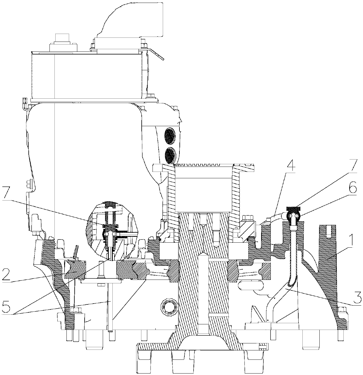
[0028] Please refer to Figure 1 to Figure 4 , figure 1 It is a structural schematic diagram of a specific embodiment of the retarder gear lubrication structure provided by the present invention; figure 2 for figure 1 A-A sectional view; image 3 It is a structural schematic diagram of a specific embodiment of the oil guide pipe provided by the present invention; Figure 4 It is ...


PUM


Abstract

The invention discloses a transmission case and a retarder gear lubrication structure thereof. The lubrication structure comprises an input oil pipe and an injection oil pipe which are arranged in a rear shell of the transmission case, and an oil guide pipe arranged outside the rear shell; the lower end of the input oil pipe is used for connecting an oil outlet of an oil pump, and the injection oil pipe is located on one side of a retarder gear; the lower end of the injection oil pipe is closed, and the injection oil pipe is provided with an oil hole; the two ends of the oil guide pipe are connected with the upper end of the input oil pipe and the upper end of the injection oil pipe separately; when the transmission case works, gear oil from the oil pump enters the rear shell through the input oil pipe, and then the gear oil is led into the injection oil pipe in the rear shell from the exterior of the rear shell, and injected onto the retarder gear through the oil hole; the forced lubrication of the retarder gear is achieved; by adopting the drainage mode of an oil pipe externally connected, lubrication oil lines are arranged simply and rationally, and are not interfered with othercomponents in the retarder gear; and the oil guide pipe can be deformed flexibly for adapting to peripheral accessories of the rear shell, so that interference is avoided.

Description

technical field [0001] The invention relates to the technical field of gearbox lubrication, in particular to a retarder gear lubrication structure of a gearbox. In addition, the present invention also relates to a gearbox comprising the above retarder gear lubricating structure. Background technique [0002] In the vehicle gearbox system, the lubrication system is mainly used to lubricate the bearings and gears in the box to prevent them from being burned, which has a direct impact on the normal operation and life of the gearbox; Auxiliary braking device, when the vehicle is decelerating or going down a long slope, the retarder is activated, which can make the heavy vehicle decelerate smoothly without consuming the braking system, and avoid the wear and heat caused by the use of brakes; with retarder The gearbox of the gearbox has a pair of transmission gears in the rear box to provide power for the retarder. [0003] At present, the ordinary splash lubrication method is s...

Claims


Application Information

Patent Timeline
Patent Type & Authority Applications(China)
IPC IPC(8): F16H57/04
CPCF16H57/042F16H57/0456
Inventor 罗海亚张澍何胜平张文涛
Owner SHANGHAI SUODA TRANSMISSION MACHINERY
Learn More