
Inflation box fixed grate bed of grate cooler

A grate cooler and air-filled box technology, applied in the direction of processing discharged materials, furnaces, lighting and heating equipment, etc., can solve the problems of fan return air, clinker ineffective cooling, material layer blowing through, etc., to improve quality and grindability, improve heat recovery efficiency, and reduce system coal consumption

Pending Publication Date: 2018-11-06
邓建新
View PDF9 Cites 2 Cited by
  • Summary
  • Abstract
  • Description
  • Claims
  • Application Information

AI Technical Summary

Problems solved by technology

The use effect of the cement clinker grate cooler mainly depends on its performance. In the current cement production, the third-generation fixed bed of the cement clinker grate cooler is composed of multi-product fixed beams. The upper plane of the fixed beams is equipped with an inflatable grate plate. The entire fixed grate bed is an independent air chamber, the fixed beam cooling air is supplied by 1 to 2 high-pressure centrifugal fans alone, and the air chamber cooling air is supplied by a high-pressure centrifugal fan alone. It is difficult to balance the air volume and air pressure with the air volume and air pressure of the air chamber fan, and it is easy for the fan to return to the air; the fourth-generation fixed bed, the entire fixed bed is an independent air chamber; due to the unreasonable structure of the traditional grate cooler, due to The discharge method of the rotary kiln is falling from a high altitude, and the high-temperature cooking that falls on the fixed grate bed produces coarse and fine segregation. The material layer at the edge is easily blown through and the phenomenon of "open air flow" occurs. Not only the grate plate and guard plate are easily damaged, but also the clinker from the grate cooler is not cooled effectively, because the high-temperature clinker cannot be cooled rapidly at the feeding end, and a reduction phenomenon occurs in the grate cooler, which affects the clinker transportation and storage , grinding and cement properties

Method used


Image

  • Inflation box fixed grate bed of grate cooler
  • Inflation box fixed grate bed of grate cooler
  • Inflation box fixed grate bed of grate cooler

Examples


Embodiment 1

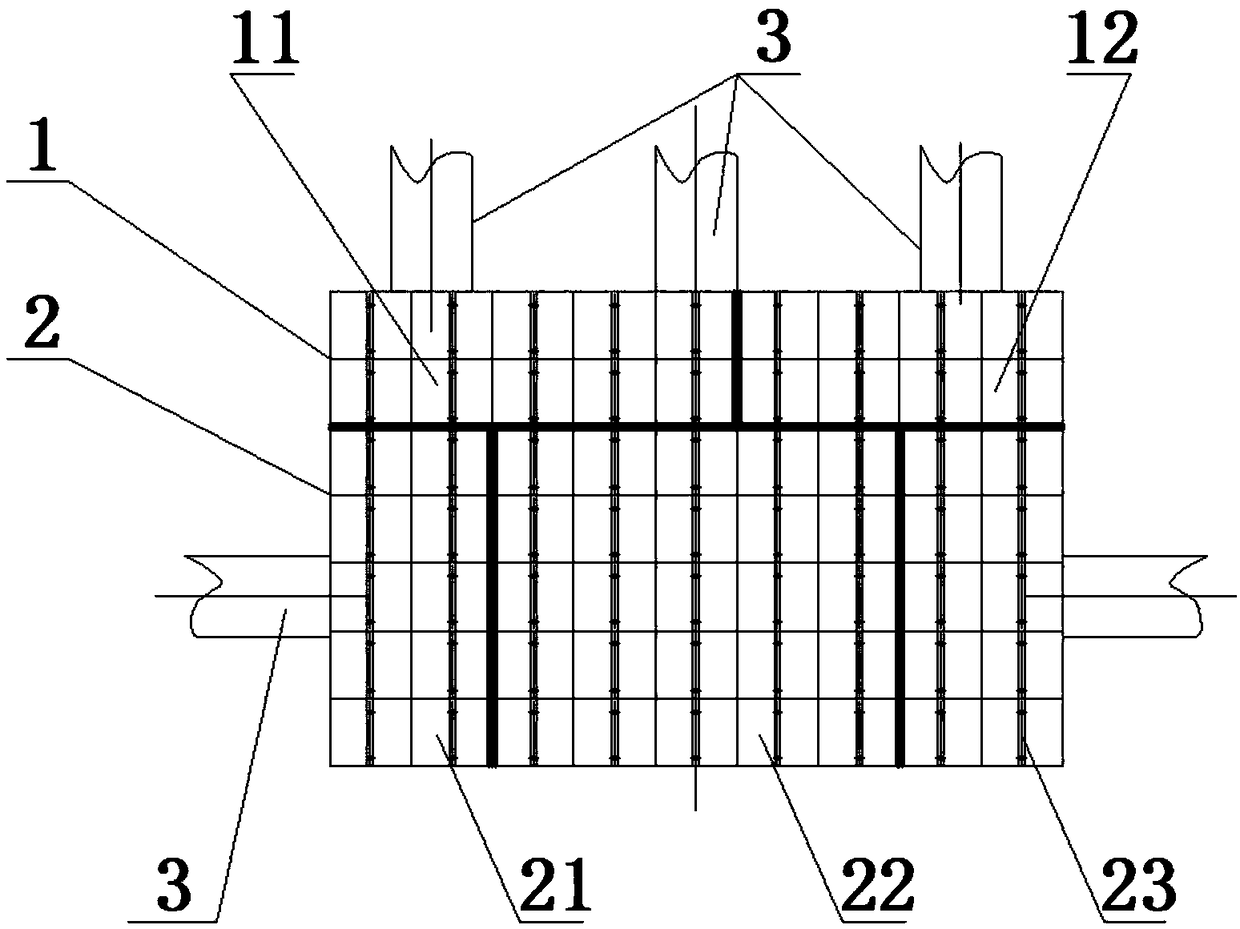
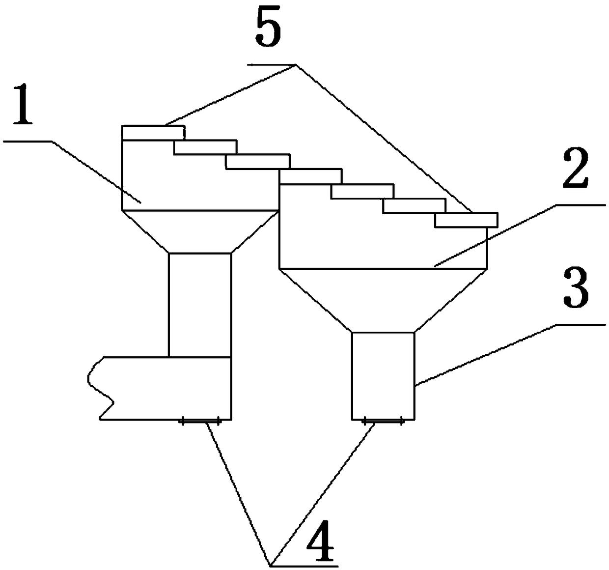
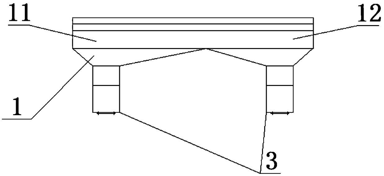
[0033] Such as Figure 1~4 Shown: a cement clinker grate cooler partition combined air box fixed grate bed,

[0034] Including a combined air box, the combined air box is composed of two combined modules arranged longitudinally, the combined module includes an air chamber and a grate plate arranged on the air chamber, and the air chambers of each combined module are equally divided It is several partitions connected with fans,

[0035] The air chamber of the end combined module 1 is divided into 2 partitions, which are the first left partition 12 and the first right partition 11 arranged horizontally; the air chamber of the non-end combined module 2 is divided into 3 partitions, which are arranged horizontally The second left partition 23, the second middle partition 22 and the third right partition are set.

[0036] The partitions are not connected, and each partition is equipped with a separate fan for air supply, and the air pressure and air volume in each partition are i...

Embodiment 2

[0040] Such as Figure 5~6 Shown: the difference between this embodiment and embodiment 1 is: a fixed grate bed of a cement clinker grate cooler partition combined inflatable box, including a combined inflatable box, the combined inflatable box is composed of two combined The combined module consists of an air chamber and a grate plate arranged on the air chamber, and the air chamber of each combined module is divided into several partitions connected with the fan, and the end combined module 1 air chamber is divided into It is two partitions, and it is the first left partition 12 and the first right partition 11 arranged horizontally; the non-end combined module 2 air chamber is divided into three partitions, and it is the second left partition 23 and the first Second middle partition 22 and third right partition.

[0041] The first left partition 12 and the first right partition 11 of the end combined module 1 communicate with the second left partition 23 and the second rig...

Embodiment 3

[0044] The difference between this embodiment and embodiment 1 or 2 is:

[0045] According to the requirements of wind pressure and air volume at different positions in each zone, divide the zone into several vertical and / or vertically arranged sub-zones. Thereby, the ability to adjust the air pressure and air volume of each partition can be improved.

[0046] At the same time, according to the number of sub-divisions of an inflatable sub-division and the air volume and wind pressure requirements of different sub-divisions, one or several air inlet pipes 3 are provided for an inflatable subdivision. All the sub-districts that make up the sub-division are set to be connected to each other; and when an air inlet pipe 3 is set for several sub-divisions, these sub-divisions are set to be connected to each other; For tube 3, set the sub-partitions to be mutually closed.


PUM


Abstract

The invention discloses a partition combined inflation box fixed grate bed of a cement clinker grate cooler. The inflation box fixed grate bed comprises a combined inflation box; the combined inflation box consists of at least two combined modules; the combined modules comprise air chambers, and grate plates arranged on the air chambers; each air chamber of each combined module is divided into multiple subareas communicating with a fan; each air chamber of each combined module at the end part of a feed end is divided into at least two subareas transversely arranged; and each air chamber of each rest non-end combined module is divided into at least three subareas transversely arranged. The fixed grate bed has the characteristics of compact structure assembly, low failure rate, high heat recovery efficiency and convenience to maintain; each air chamber of each combined module of the fixed grate bed is divided into multiple subareas; and aiming at different material layer thicknesses anddifferent material layer porosities, corresponding reasonable air volumes and air pressures are set.

Description

technical field [0001] The invention relates to an air-filled box-fixed grate bed of a grate cooler, in particular to a cement clinker grate cooler fixed grate bed with partitioned and combined air-filled boxes. Background technique [0002] The cement clinker grate cooler is an important thermal process equipment in the cement clinker production line of the cement plant. Conveying, storage, grinding and cement properties. The use effect of the cement clinker grate cooler mainly depends on its performance. In the current cement production, the third-generation fixed bed of the cement clinker grate cooler is composed of multi-product fixed beams. The upper plane of the fixed beams is equipped with an inflatable grate plate. The entire fixed grate bed is an independent air chamber, the fixed beam cooling air is supplied by 1 to 2 high-pressure centrifugal fans alone, and the air chamber cooling air is supplied by a high-pressure centrifugal fan alone. It is difficult to bala...

Claims


Application Information

Patent Timeline
Patent Type & Authority Applications(China)
IPC IPC(8): F27D15/02
CPCF27D15/022F27D2015/0233
Inventor 邓建新
Owner 邓建新
Learn More