
Two-dimensional positioning method for intelligent car based on machine vision and regional feature extraction

A technology of machine vision and regional features, applied in the field of target positioning, can solve the problem of non-detection and achieve the effect of improving efficiency and speed

Active Publication Date: 2018-11-06
NANJING UNIV OF POSTS & TELECOMM
View PDF4 Cites 0 Cited by
  • Summary
  • Abstract
  • Description
  • Claims
  • Application Information

AI Technical Summary

Problems solved by technology

Obviously, the internal gray value of MSER detected in this way is smaller than the boundary. Imagine a picture of a white area with a black background. Obviously, this area cannot be detected.

Method used


Image

  • Two-dimensional positioning method for intelligent car based on machine vision and regional feature extraction
  • Two-dimensional positioning method for intelligent car based on machine vision and regional feature extraction
  • Two-dimensional positioning method for intelligent car based on machine vision and regional feature extraction

Examples


Embodiment Construction

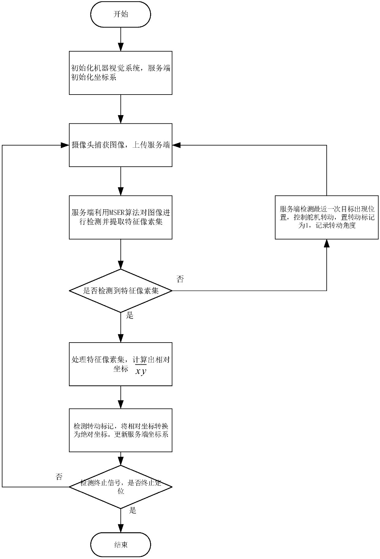
[0033]The single target two-dimensional positioning method based on machine vision and regional feature extraction of the present invention comprises the following steps:

[0034] Step 1) Set LED lights for the smart car to be positioned as the characteristic mark of the smart car, given the target operating domain O, and place the machine vision device in the center of the operating domain O, the machine vision device is used to collect images Dual camera C. 1 with C 2 , used to control the dual camera C 1 with C 2 Composed of rotating steering gear and computing system for processing image information;

[0035] Step 2) Start the machine vision device, and the computing system is set up with dual cameras C 1 and C 2 The connecting line is the x-axis, so as to be perpendicular to C 1 and C 2 The straight line at the midpoint of the connection is the Cartesian coordinate system of the y-axis, and the timing T is set n =T 0 , set the rotation mark I=0, place the smart c...


PUM


Abstract

The invention discloses a two-dimensional positioning method for an intelligent car based on machine vision and regional feature extraction. Two-dimensional positioning of a target is realized according to a triangle relationship between feature point coordinate information extracted from an image captured by a vision sensor and parameters of the vision sensor. According to the two-dimensional positioning method disclosed by the invention, feature point extraction is realized by utilizing a regional feature extraction technology, and an accurate coordinate position is obtained by mean value calculation, so that the interference of noisy points on feature points can be effectively reduced. The invention also provides a coordinate system projection algorithm which can extend and fix a visualangle of the vision sensor.

Description

technical field [0001] The invention relates to the field of target positioning, and relates to a target positioning method based on machine vision and feature recognition. Background technique [0002] Machine vision is to use machines to replace human eyes for measurement and judgment. Through machine vision products (ie, image capture devices. There are two types of CMOS and CCD), the captured objects are converted into image signals and sent to a dedicated image processing system. According to Pixel distribution, color, grayscale and other information are converted into digital signals; the image system performs various operations on these signals to extract the characteristics of the target, and then controls the on-site equipment actions according to the results of the discrimination. [0003] Machine vision technology has the potential to be used as a positioning function. It can automatically judge the position of an object according to the mathematical relationship ...

Claims


Application Information

Patent Timeline
IPC IPC(8): G01C11/02G01C11/04
CPCG01C11/02G01C11/04
Inventor 陈志汪皓平岳文静狄小娟王福星
Owner NANJING UNIV OF POSTS & TELECOMM
Learn More