
Dynamic working condition system of pollution source and using method thereof

A pollution source and dynamic technology, applied in general control systems, control/regulation systems, and comprehensive factory control, etc., can solve problems such as the inability to effectively curb the phenomenon of fraud, the inability to supervise the production and pollution control process data of enterprises, and data fraud, etc., to reduce Exchange the frequency of verification and on-site inspection, optimize the allocation of resources, and prevent the effect of stealing discharge

Active Publication Date: 2018-11-06
江苏三希科技股份有限公司
View PDF13 Cites 11 Cited by
  • Summary
  • Abstract
  • Description
  • Claims
  • Application Information

AI Technical Summary

Problems solved by technology

[0003] However, with the further deepening of environmental protection work, people found that sometimes the figures in the report did not match the actual situation
Falsification of online monitoring data of pollution sources occurs from time to time
Since 2013, a provincial environmental protection department has investigated and dealt with 22 companies that damaged or interfered with online monitoring facilities and falsified monitoring data. However, the system reform, independent investigation, and severe punishment cannot effectively curb the phenomenon of fraud
Since the current system focuses more on the dynamic management and control of the sewage discharge situation of enterprises, it is unable to supervise the production and pollution control process data of enterprises

Method used

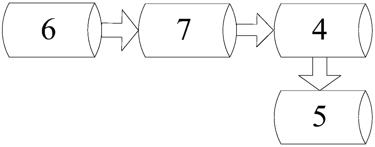
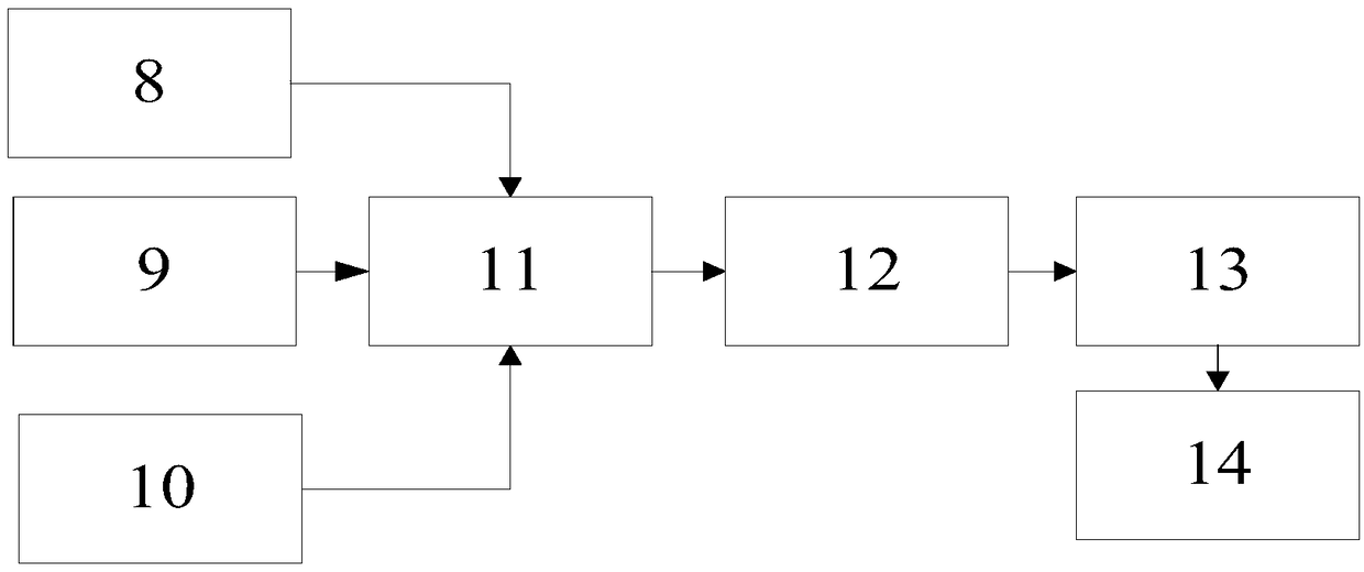

Image

  • Dynamic working condition system of pollution source and using method thereof
  • Dynamic working condition system of pollution source and using method thereof
  • Dynamic working condition system of pollution source and using method thereof

Examples


Embodiment Construction

[0033] The present invention will be further described below in conjunction with the accompanying drawings. The following examples are only used to illustrate the technical solution of the present invention more clearly, but not to limit the protection scope of the present invention.

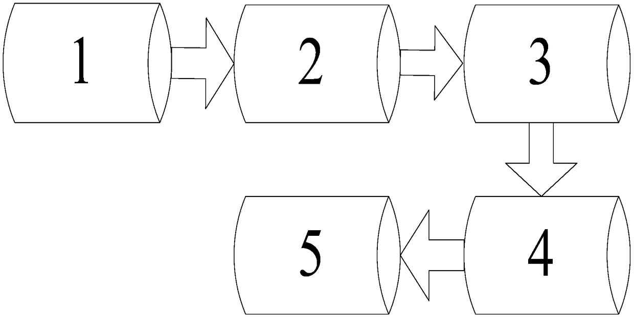
[0034] figure 1 It is a flow diagram of the existing exhaust gas pollution source monitoring system, including: exhaust gas sampling system 1, flue gas analysis system 2, industrial computer or PLC3, data acquisition and transmission instrument 4, and monitoring platform 5.

[0035] Exhaust gas sampling system 1 is mainly composed of hardware equipment, such as sampling probes, sampling pipelines, etc., to realize the functions of sample gas sampling, heat-tracing transmission to the flue gas analysis system, dehumidification and dust filtering, and is divided into extraction sampling method and direct measurement method.

[0036] The flue gas analysis system 2 is mainly composed of a gaseous p...


PUM


Abstract

The invention discloses a dynamic working condition system of a pollution source. The dynamic working condition system is composed of a field collecting terminal, an internet-of-things transmission terminal and an application platform side. The output terminal of the field collecting terminal is connected with the input terminal of the internet-of-things transmission terminal; and the output terminal of the internet-of-things transmission terminal is connected with the input terminal of the application platform side. In addition, the invention also provides a using method of the dynamic working condition system of a pollution source. The environmental protection department carries out remote monitoring, early warning, and law enforcement under the big data background, so that the production state of the enterprise and the operation state of the pollution control facility are monitored in real time; remote supervision and intelligent supervision on enterprises by the environmental supervision department are enhanced and the frequency of exchange inspection and on-site inspection by the environmental supervision staff is reduced, so that the work efficiency of government departmentsis improved; and the decision-making base is provided for eliminating the backward production capacity, controlling the total discharge amount, optimizing the resource configuration, and improving theliving environment.

Description

technical field [0001] The invention relates to a pollution source dynamic working condition system and a use method, belonging to the technical field of intelligent environmental protection monitoring. Background technique [0002] Since 2007, the country has begun to implement the networking scheme of automatic online monitoring equipment for pollution sources. Up to now, the number of installed online points has reached 100,000. The world's largest pollution source monitoring system. These online monitoring devices become the "clairvoyance" of environmental supervisors. [0003] However, with the further development of environmental protection work, people found that sometimes the figures in the report did not match the actual situation. Falsification of online monitoring data of pollution sources occurs from time to time. Since 2013, a provincial environmental protection department has investigated and dealt with 22 enterprises that damaged or interfered with online m...

Claims


Application Information

Patent Timeline
IPC IPC(8): G05B19/418G01D21/02
CPCG01D21/02G05B19/4183G05B2219/31282Y02P90/02
Inventor 潘成欣包汉举宋健
Owner 江苏三希科技股份有限公司
Learn More