Damping and cooling structure of case fan

A heat dissipation structure and fan technology, applied in the direction of instruments, electrical digital data processing, digital data processing components, etc., can solve the problems of poor fan installation structure stability, unsatisfactory heat dissipation performance, and stability performance to be improved. It is not easy to achieve Effects of vibration and noise, avoidance of clogging, improvement of stability performance

Inactive Publication Date: 2018-11-06
湖州旭源电气科技有限公司
View PDF8 Cites 1 Cited by
  • Summary
  • Abstract
  • Description
  • Claims
  • Application Information

AI Technical Summary

Problems solved by technology

Existing chassis generally use fans to dissipate heat. However, the fan itself generates heat when it is working, and the heat is not easy to dissipate, resulting in increased heat in the chassis. Moreover, the installation structure of many fans is not stable. When the fan is running at a high , the faster the rotation speed, the greater the vibration, and air and mechanical noise will be generated. Therefore, the fan structure in the existing frequency conversion chassis has the problems of unsatisfactory heat dissipation performance, stable performance to be improved, and easy vibration and noise.

Method used


Image

  • Damping and cooling structure of case fan
  • Damping and cooling structure of case fan
  • Damping and cooling structure of case fan

Examples


Embodiment Construction

[0015] The present invention will be further described below in conjunction with the accompanying drawings and embodiments, but not as a basis for limiting the present invention.

[0016] Example.

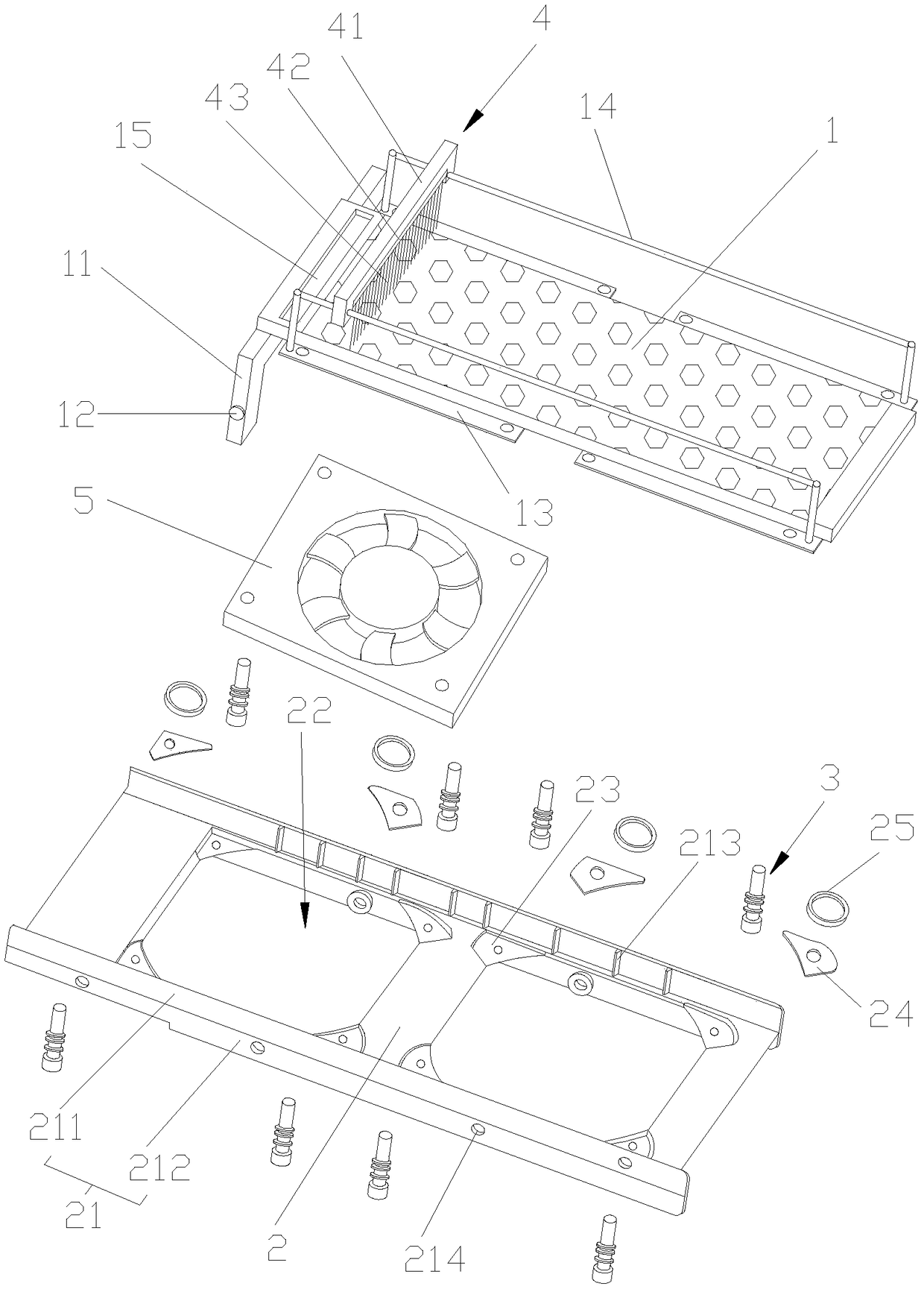
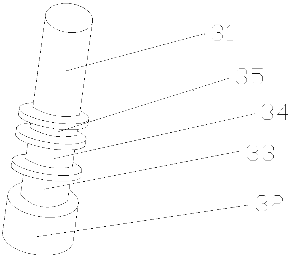
[0017] like figure 1 , figure 2 and image 3 As shown, a shock-absorbing and heat-dissipating structure of a chassis fan includes a mounting plate 2, a filter plate 1 is arranged above the mounting plate 2, and a plurality of air vents 22 for installing fans 5 are arranged on the mounting plate 2. The mounting plate 2, the periphery of the vent 22 is provided with a number of shock absorbing grooves 23, the bottom surface of the shock absorbing groove 23 is provided with heat dissipation silica gel 24, the side of the shock absorbing groove 23 is provided with a buffer ring 25, and the shock absorbing groove 23 A shock-absorbing nail 3 is provided inside, and the shock-absorbing nail 3 passes through the heat dissipation silica gel 24, the fan 5 and the filter plate 1 in turn; ...


PUM


Abstract

The invention discloses a damping and cooling structure of a case fan. The damping and cooling structure comprises a mounting plate; a filtering plate is arranged above the mounting plate; a pluralityof vent holes for mounting fans are formed in the mounting plate; a plurality of damping grooves are formed around the vent holes in the mounting plate; cooling silica gel is arranged on the bottom surfaces of the damping grooves; buffer rings are arranged on the side surfaces of the damping grooves; damping screws are arranged in the damping grooves in a penetrating mode; the damping screws sequentially penetrate through the cooling silica gel, the fans and the filtering plate; a rotating arm is arranged at one end of the filtering plate; the rotating arm is rotationally connected with the mounting plate; fixed pieces connected with the damping screws are arranged on the front side and the rear side of the filtering plate respectively; sliding rods arranged in the length direction of thefiltering plate are arranged above the fixed pieces; a cleaning brush strip arranged in the width direction of the filtering plate is arranged on the sliding rods; and the two ends of the cleaning brush strip are in sliding connection with the sliding rods. The damping and cooling structure has the characteristics of good cooling performance, high stability and difficulty in generating vibrationand noises.

Description

technical field [0001] The invention relates to a fan structure, in particular to a shock-absorbing and heat-dissipating structure of a chassis fan. Background technique [0002] In the prior art, the chassis contains a large number of electronic components, which generate a large amount of heat during operation, and the accumulation of heat will damage the electronic components and circuits. Therefore, the chassis requires relatively high heat dissipation performance. Existing chassis generally use fans to dissipate heat. However, the fan itself generates heat when it is working, and the heat is not easy to dissipate, resulting in increased heat in the chassis. Moreover, the installation structure of many fans is not stable. When the fan is running at a high , the faster the rotation speed, the greater the vibration, and air and mechanical noise will be generated. Therefore, the fan structure in the existing frequency conversion chassis has the problems of unsatisfactory he...

Claims


Application Information

Patent Timeline
Patent Type & Authority Applications(China)
IPC IPC(8): G06F1/20G06F1/18
CPCG06F1/183G06F1/20
Inventor 黄雪冰
Owner 湖州旭源电气科技有限公司
Why Eureka
Try Eureka