
Bionic eye device

A bionic eye and eyeball technology, which is applied in the field of bionic eye devices, can solve the problems of stuck recognition process and long recognition time, and achieve the effect of improving representation and accuracy

Pending Publication Date: 2018-11-06
卫芯科技(浙江)有限公司
View PDF3 Cites 0 Cited by
  • Summary
  • Abstract
  • Description
  • Claims
  • Application Information

AI Technical Summary

Problems solved by technology

Among them, static image recognition is to collect a single image of the object to be recognized, and compare the characteristics of this single image with the pre-stored image to realize the recognition of the object to be recognized; however, because it only uses a single image, it is easy to use pre-prepared The photo of the object to be recognized is replaced by the object to be recognized; the dynamic video recognition is to collect the dynamic video of the object to be recognized, and compare the characteristics of multiple images in the dynamic video with the pre-stored images to realize the recognition of the object to be recognized. Although, it avoids In the static image recognition, photos are used to fool the recognition. However, multiple dynamic images are compared with the pre-stored images respectively, and the recognition time is too long, and even the recognition process is stuck.

Method used


Image

  • Bionic eye device
  • Bionic eye device
  • Bionic eye device

Examples


Embodiment 1

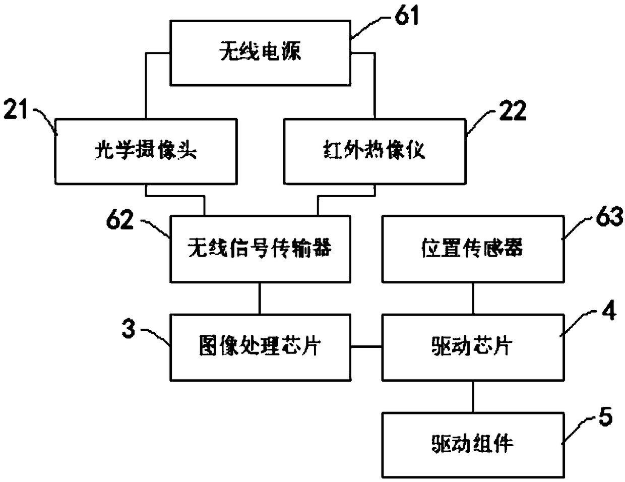
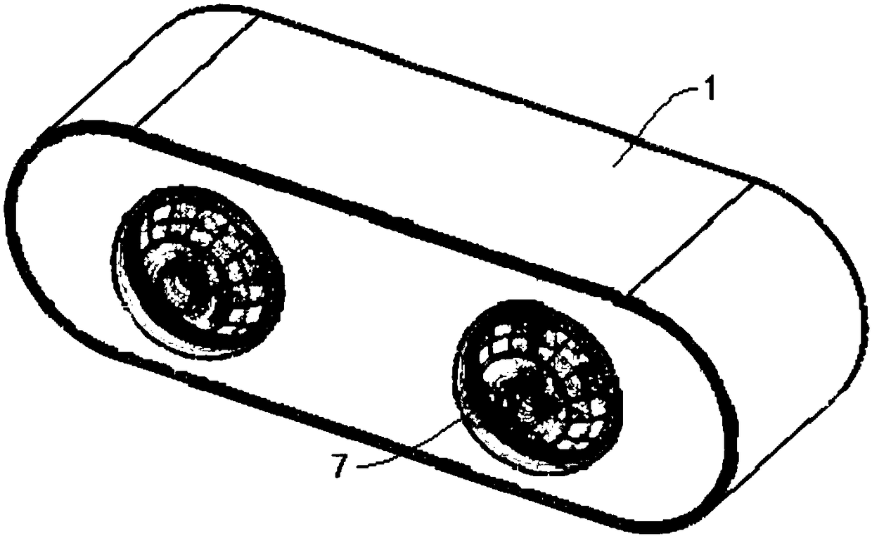
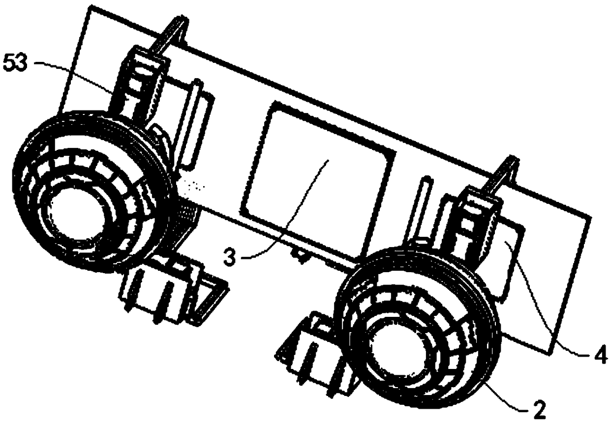
[0039] like figure 1 As shown, a bionic eye device in Embodiment 1 of the present invention includes a housing 1, and two bionic eyeballs 2 are embedded on the housing 1, wherein one bionic eyeball 2 is an optical camera 21, and the other bionic eyeball 2 is an infrared thermal sensor. Imager 22; also includes an image processing chip 3; in specific implementation, in order to facilitate the heat dissipation of the image processing chip 3, the material of the housing 1 can be aluminum, and the circuit board with the image processing chip 3 can be attached to the housing 1 inside of the rear panel;

[0040] Optical camera 21, which is used to collect the optical view of the object to be identified;

[0041] Infrared thermal imaging camera 22, which is used to collect the infrared thermal image of the object to be identified;

[0042] The image processing chip 3 is used to fuse the optical view and the infrared heat map to generate a captured image, and compare the features of...

Embodiment 2

[0044] Embodiment 2 of the present invention is a bionic eye device. On the basis of Embodiment 1, the bionic eye device further includes a drive chip 4 and two drive components 5, and each drive component 5 corresponds to a bionic eyeball 2;

[0045] The image processing chip 3 is also used to generate a field of view movement signal when the field of view direction corresponding to the captured image does not match the field of view direction corresponding to the prestored image;

[0046] A driving chip 4, which is used to generate a first driving signal according to the field of view movement signal;

[0047] The driving component 5 is used to drive the corresponding bionic eyeball 2 to rotate according to the first driving signal, thereby changing the direction of the field of view of the collected image, so that the direction of the field of view of the collected image matches the direction of the field of view of the pre-stored image.

[0048]For example, in the process ...

Embodiment 3

[0051] Embodiment 3 of the present invention is a bionic eye device. On the basis of Embodiment 2, the bionic eyeball 2 is a sphere; Equal-radius balls 52, two annular tracks 51 are sleeved on both sides of the center plane of the corresponding bionic eyeball 2, and the two annular tracks 51 are fixedly arranged in the housing 1, and the balls 52 in the two annular tracks 51 are both The corresponding bionic eyeball 2 is circumscribed.

[0052] Wherein, the central plane of the bionic eyeball 2 is the plane passing through the center of the sphere of the bionic eyeball 2 . This structure makes the bionic eyeball 2 rotate in the circular track 51 under the promotion of external force, the ball center of the bionic eyeball 2 is still relative to the two circular track 51, that is, it is stationary relative to the housing 1, so as to prevent the bionic eyeball 2 from rotating during the rotation process. Shell 1 falls off.

[0053] In specific implementation, the structure of t...


PUM


Abstract

The invention relates to a bionic eye device. Two bionic eyeballs are an optical camera and an infrared thermal imager respectively, and an image processing chip performs feature comparison on an acquired image generated by fusing an optical view acquired by the optical camera and an infrared thermal image acquired by the infrared thermal imager with a prestored image so as to achieve recognitionof an object to be recognized; the bionic eyeballs can correct the initial positions under the actions of driving chips, driving assemblies and position sensors and can flexibly rotate according to the position of the object to be recognized in the recognition process; an indicating lamp is arranged in front of the bionic eyeballs, so that quick knowing of a recognition result is facilitated; theoptical camera is a wide-dynamic and low-illumination camera and can be a RGB color camera and a high-speed zoom camera, so that improvement on the image quality and the acquisition speed of the acquired optical view is facilitated; when the bionic eye device is applied to intelligent recognition, the speed of acquiring and processing a target image in motion is increased, the visual field is wideand flexible, and the image recognition efficiency is further improved.

Description

technical field [0001] The invention relates to the technical field of intelligent identification, in particular to a bionic eye device. Background technique [0002] Existing intelligent recognition usually adopts static image recognition or dynamic fixed video recognition modules. Among them, static image recognition is to collect a single image of the object to be recognized, and compare the characteristics of this single image with the pre-stored image to realize the recognition of the object to be recognized; however, because it only uses a single image, it is easy to use pre-prepared The photo of the object to be recognized is replaced by the object to be recognized; the dynamic video recognition is to collect the dynamic video of the object to be recognized, and compare the characteristics of multiple images in the dynamic video with the pre-stored images to realize the recognition of the object to be recognized. Although, it avoids It has solved the situation that p...

Claims


Application Information

Patent Timeline
Patent Type & Authority Applications(China)
IPC IPC(8): G06K9/00G06K9/20H04N5/225H04N9/04
CPCG06V40/172G06V20/30G06V10/10H04N23/51H04N23/10
Inventor 张宏鑫其他发明人请求不公开姓名
Owner 卫芯科技(浙江)有限公司
Learn More