Damping pedestal with movement function applied to installation of electric cabinet

A technology of mobile function and shock-absorbing base, applied in electrical components, seismic equipment, substation/switch layout details, etc., can solve the problems of power cabinet vibration, no shock-absorbing function, unstable working state of components, etc., to reduce labor intensity , good normal use, improve the effect of efficiency

Inactive Publication Date: 2018-11-06
陈汉军
View PDF0 Cites 13 Cited by
  • Summary
  • Abstract
  • Description
  • Claims
  • Application Information

AI Technical Summary

Problems solved by technology

[0005] Aiming at the deficiencies of the prior art, the present invention provides a shock-absorbing base with a moving function for placing the power cabinet, which solves the problem that most of the current shock-absorbing bases do not have the function of moving the base. When the power cabinet needs to be moved , requires the staff to move the power cabinet and the base separately, which increases the labor intensity of the staff and affects the efficiency of moving the power cabinet, and most of the existing power cabinet moving devices do not have a shock absorption function. The process will cause vibration of the components in the power cabinet, resulting in unstable working status of the components, which will affect the normal use of the power cabinet

Method used


Image

  • Damping pedestal with movement function applied to installation of electric cabinet
  • Damping pedestal with movement function applied to installation of electric cabinet

Examples


Embodiment Construction

[0024] The following will clearly and completely describe the technical solutions in the embodiments of the present invention with reference to the accompanying drawings in the embodiments of the present invention. Obviously, the described embodiments are only some, not all, embodiments of the present invention. Based on the embodiments of the present invention, all other embodiments obtained by persons of ordinary skill in the art without making creative efforts belong to the protection scope of the present invention.

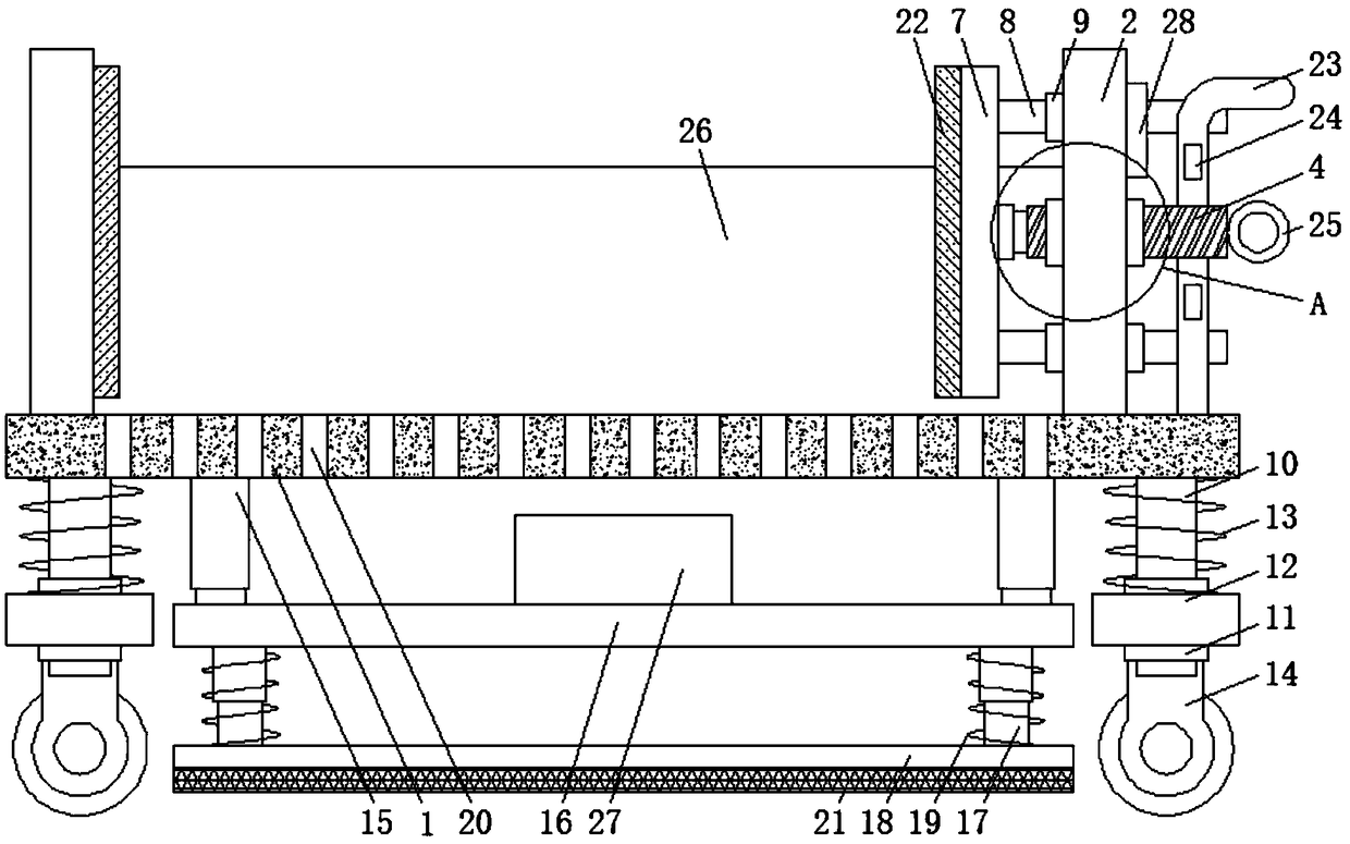
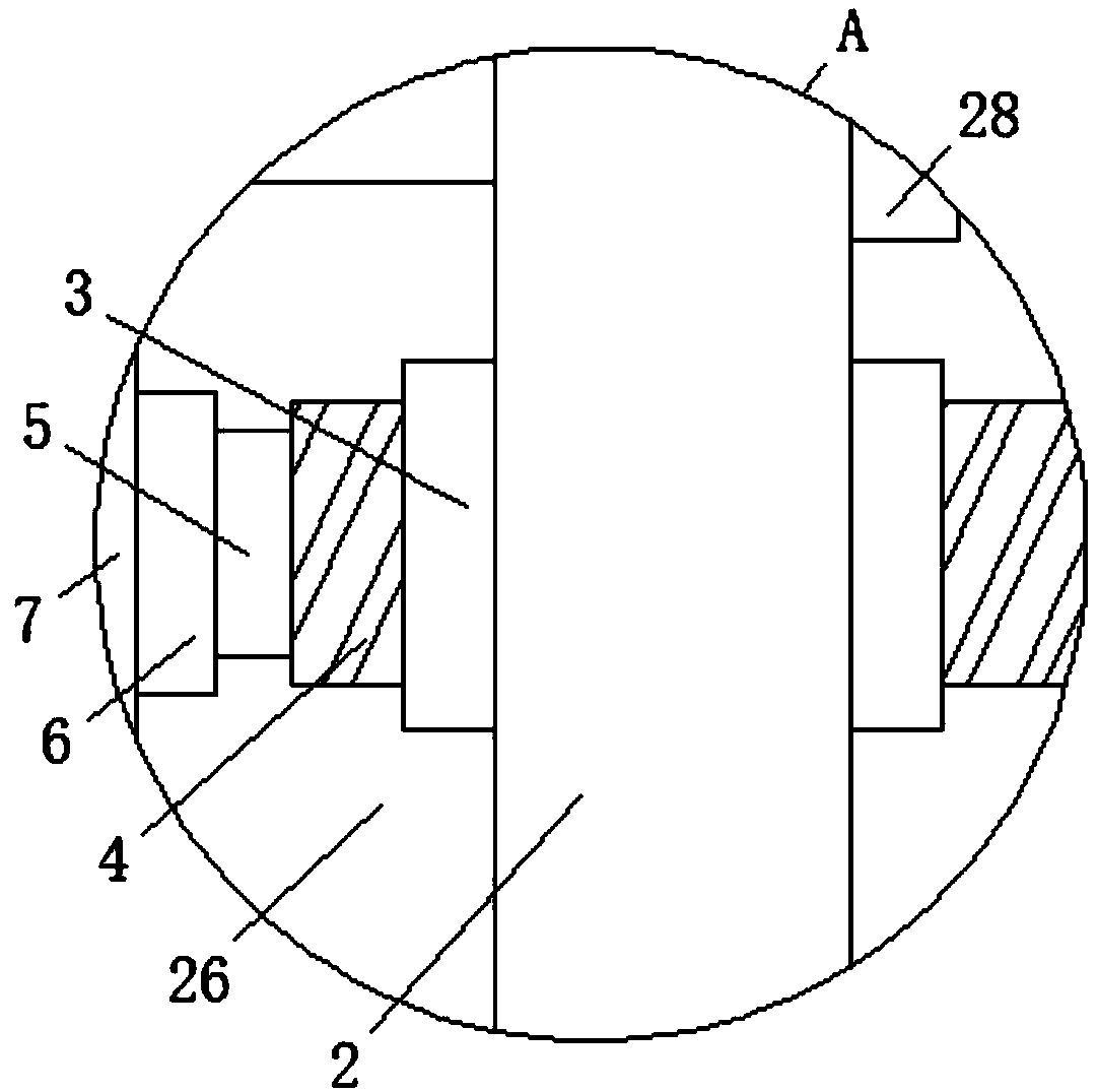
[0025] Such as Figure 1-2As shown, the present invention provides a technical solution: a shock-absorbing base with a moving function for placing a power cabinet, including a support plate 1, the left and right sides of the upper surface of the support plate 1 are fixedly connected with the first fixed plate 2, The upper surface of the support plate 1 is provided with several through holes 20, and the through holes 20 are located between the two first fixed p...


PUM


Abstract

The invention discloses a damping pedestal with a movement function applied to the installation of an electric cabinet. The damping pedestal comprises a support plate, wherein first fixing plates arefixedly connected with left and right sides of the upper surface of the support plate, a screw cylinder is connected with the right side face of the first fixing plate on the right side in a clampingmanner, a screw column is in threaded connection with the interior of the screw cylinder, the left end of the screw column is fixedly connected with the right end of a rotation shaft, and bearing is connected with the surface of the rotation shaft in a sleeving manner. The damping pedestal with the movement function applied to the installation of the electric cabinet, through the arrangement of the screw cylinder, screw column, clamping plate, first spring, idler wheels, electric push rod and second spring, the support plate and the electric cabinet can be better moved via the idler wheels, the labor intensity of the staffs is reduced, the movement efficiency of the electric cabinet is improved, and meanwhile, the impact force generated by vibration of the support plate can be buffered byusing the first spring and the second spring, so that the elements in the electric cabinet can be prevented from vibrating, and thus the electric cabinet can be better normally used.

Description

technical field [0001] The invention relates to the technical field of power equipment, in particular to a shock-absorbing base with a moving function for placing a power cabinet. Background technique [0002] The power cabinet is divided into power power cabinet, lighting power cabinet and metering cabinet. It is the final equipment of the power distribution system. The power cabinet is the general name of the motor control center. It is used in the occasions where the load is concentrated and there are many circuits. They distribute the electric energy of a certain circuit of the upper-level power distribution equipment to the nearby loads. This level of equipment should provide protection, monitoring and control for the loads. [0003] Most of the power cabinets are placed on the shock-absorbing base for use. Most of the current shock-absorbing bases do not have the function of moving the base. When the power cabinet needs to be moved, the staff needs to move the power ca...

Claims


Application Information

Patent Timeline
Patent Type & Authority Applications(China)
IPC IPC(8): H02B1/54H02B1/52
CPCH02B1/54H02B1/52
Inventor 陈汉军
Owner 陈汉军
Why Eureka
Try Eureka