Unlock instant, AI-driven research and patent intelligence for your innovation.
Iron core and disk type motor
What is Al technical title?
Al technical title is built by PatSnap Al team. It summarizes the technical point description of the patent document.
A disc motor and iron core technology, applied in the field of motor parts, can solve problems such as high energy consumption and high current
Pending Publication Date: 2018-11-06
SHANGHAI PANGOOD POWER TECH CO LTD
View PDF0 Cites 0 Cited by
Summary
Abstract
Description
Claims
Application Information
AI Technical Summary
This helps you quickly interpret patents by identifying the three key elements:
Problems solved by technology
Method used
Benefits of technology
Problems solved by technology
[0003] However, when the disc motor is under field-weakening control, it needs a large current and consumes a lot of energy
Method used
Image
Click on the blue label to locate the original text in one second.
Reading with bidirectional positioning of images and text.
Examples
Embodiment 1
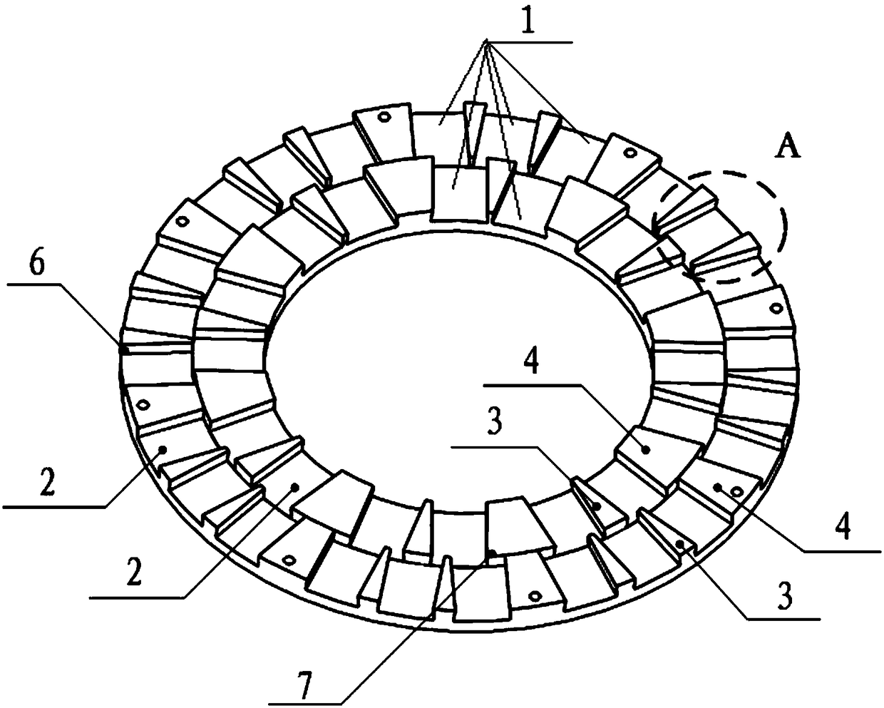
[0048] Such as Figure 1-6 As shown, the present invention provides an iron core. It can be used in the middle stator, two side rotors or single stator, single rotor or cascaded disc motor structure.
[0049] Wherein, multiple groups of magnetic steel installation positions 1 are evenly distributed along the circumferential direction of the iron core on the iron core.
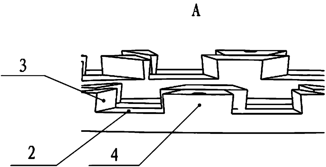
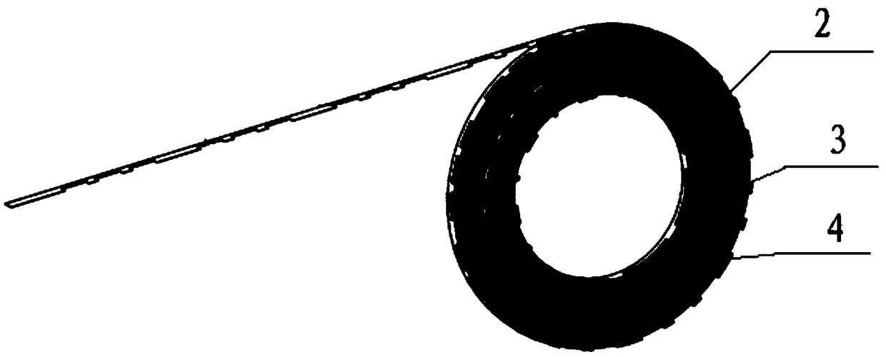
[0050] Each group of magnetic steel installation positions 1 includes a plurality of steel grooves 2 for installing magnetic steel 5 . And along the circumferential direction of the iron core, the first iron core teeth 3 are arranged between the adjacent steel grooves 2 of the same group of magnetic steel installation positions 1, and the steel grooves 2 of the same group of magnetic steel installation positions 1 are used to install the same Magnetic poles of magnetic steel 5.
[0051] The second iron core teeth 4 are arranged between adjacent groups of magnetic steel installation positions 1, and the steel...
Embodiment 2
[0056] In the second embodiment provided by the present invention, the structure of the iron core in this embodiment is similar to the iron core in the first embodiment, so the similarities will not be repeated, and only the differences will be introduced.
[0057] In this embodiment, the present invention specifically discloses that along the axial direction of the iron core, the thickness of the second iron core teeth 4 is greater than the thickness of the first iron core teeth 3 .
[0058]The second iron core tooth 4 on the iron core can increase the q-axis inductance of the motor (the inductance is proportional to the magnetic permeability of the magnetic field loop, and the magnetic flux path that generates the q-axis inductance needs to pass through the middle axis between adjacent magnetic poles of different polarities , because the second iron core tooth 4 is located on the magnetic flux path, therefore, the magnetic permeability of the magnetic field circuit can be inc...
Embodiment 3
[0075] The present invention provides a disc motor, including a magnetic steel 5 and an iron core as in any one of the above-mentioned embodiments. The magnetic steel 5 is installed in the steel groove 2 of the iron core.
[0076] Since the disc motor disclosed in the present invention includes the iron core in any one of the above embodiments, all the beneficial effects of the iron core are included in the disc motor disclosed in the present invention.
PUM
Abstract
The invention discloses an iron core and a disk type motor. Multiple groups of magnetic steel mounting sites are distributed on the iron core along the circumferential direction of the iron core uniformly; each group of magnetic steel mounting sites comprises a plurality of steel tanks; along the circumferential direction of the iron core, first iron core teeth are arranged between the adjacent steel tanks of the same group of the magnetic steel mounting sites; the steel tanks of the same group of magnetic steel mounting sites are used for mounting magnetic steel with the like magnetic pole; second iron core teeth are arranged between the adjacent group of magnetic steel mounting sites; and the steel tanks of the adjacent group of magnetic steel mounting sites are used for mounting magnetic steel with opposite magnetic poles. Each group of magnetic steel mounting sites comprises a plurality of steel tanks, and the same group of steel tanks are partitioned by the first iron core teeth along the circumferential direction of the iron core, so that the d-axis inductance is enhanced. When the motor performs weak magnetic control at high speed, the size of the needed current can be obviously reduced under the same voltage when the d-axis inductance of the motor is increased, or the highest weak magnetic rotating speed which the motor can reach to can be significantly increased.
Description
technical field [0001] The invention relates to the technical field of motor components, in particular to an iron core and disc motor. Background technique [0002] Radial field motors and axial field motors (also called disc motors) are two major branches of the motor field. Disk motors are more and more widely used because of their higher iron core utilization, higher power density and higher torque density. [0003] However, when the disc motor is under field-weakening control, it needs a large current and consumes a lot of energy. [0004] Therefore, how to reduce the current required by the disc motor when performing field weakening control is a technical problem to be solved urgently by those skilled in the art. Contents of the invention [0005] In view of this, the first object of the present invention is to provide an iron core that can reduce the current required by the disc motor when field weakening control is performed. [0006] A second object of the prese...
Claims
Application Information
Patent Timeline
Application Date:The date an application was filed.
Publication Date:The date a patent or application was officially published.
First Publication Date:The earliest publication date of a patent with the same application number.
Issue Date:Publication date of the patent grant document.
PCT Entry Date:The Entry date of PCT National Phase.
Estimated Expiry Date:The statutory expiry date of a patent right according to the Patent Law, and it is the longest term of protection that the patent right can achieve without the termination of the patent right due to other reasons(Term extension factor has been taken into account ).
Invalid Date:Actual expiry date is based on effective date or publication date of legal transaction data of invalid patent.

