Double-motor driven mechanical clamp for injection molding machine

A dual-motor drive and mechanical clamp technology, which is applied in the direction of manipulators, chucks, manufacturing tools, etc., can solve the problems of easy vibration of clamps, affecting the precision of injection molding machines, and low stability, so as to improve operation accuracy, stabilize vibration, and avoid The effect of dislocation

Inactive Publication Date: 2018-11-09
华文进
View PDF0 Cites 2 Cited by
  • Summary
  • Abstract
  • Description
  • Claims
  • Application Information

AI Technical Summary

Problems solved by technology

Mechanical clamps are commonly used on injection molding machines. At present, the stability of mechanical clamps used in injection

Method used


Image

  • Double-motor driven mechanical clamp for injection molding machine

Examples


Embodiment Construction

[0011] The preferred embodiments of the present invention will be described in detail below in conjunction with the accompanying drawings, so that the advantages and features of the present invention can be more easily understood by those skilled in the art, so as to define the protection scope of the present invention more clearly.

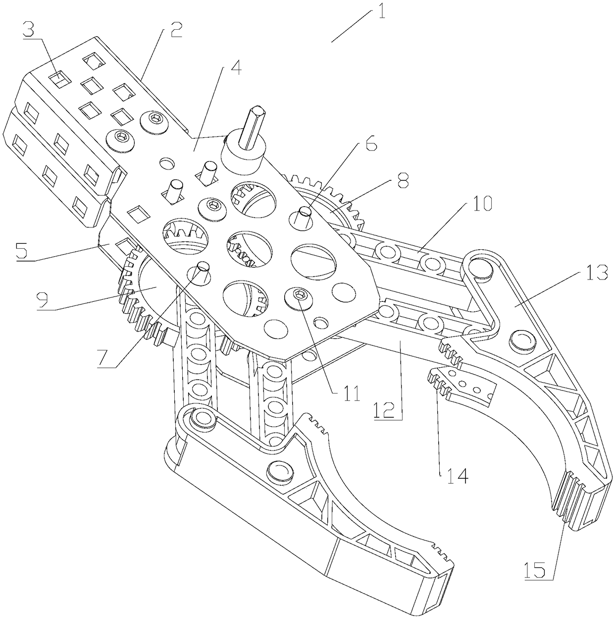
[0012] Such as figure 1 As shown, a dual-motor-driven mechanical clamp 1 for an injection molding machine includes a connecting sleeve 2, a plurality of fixing screw holes 3 are provided on the connecting sleeve 2, and an upper splint 4 is fixedly connected to the connecting sleeve 2 With the lower splint 5, the upper splint 4 and the lower splint 5 are parallel to each other, a first rotating shaft 6 and a second rotating shaft 7 are connected between the upper splint 4 and the lower splint 5, and the first rotating shaft 6 and the second rotating shaft The end of 7 is used for connecting drive motor, and a first gear 8 is fixedly connected on t...


PUM


Abstract

The invention discloses a double-motor driven mechanical clamp for an injection molding machine. The double-motor driven mechanical clamp for the injection molding machine is characterized in that tworotating shafts are arranged on a body, the two rotating shafts are driven by two independent motors, and the two rotating shafts are connected by a pair of gears, so two driving units are in engagedwith each other, misalignment between the two driving units is avoided, the clamp is stable and is not prone to vibrate during the clamping operation, and the improvement of the working precision ofthe injection molding machine is benefited.

Description

technical field [0001] The invention relates to a double-motor-driven mechanical clamp for an injection molding machine. Background technique [0002] Injection molding machine is also known as injection molding machine or injection machine. It is the main molding equipment for making thermoplastics or thermosetting plastics into various shapes of plastic products using plastic molding molds. Divided into vertical, horizontal, all-electric. The injection molding machine heats the plastic, applies high pressure to the molten plastic, and makes it shoot out to fill the mold cavity. Mechanical clamps are widely used on injection molding machines. The stability of mechanical clamps used in injection molding machines is not high at present. The clamps are easy to vibrate during use, which affects the precision of injection molding machines. Contents of the invention [0003] The present invention mainly solves the technical problems existing in the prior art, thereby providi...

Claims


Application Information

Patent Timeline
IPC IPC(8): B29C45/42B25J15/02
CPCB29C45/4225B25J15/026
Inventor 华文进
Owner 华文进
Why Eureka
Try Eureka