Wireless charging mobile phone and mobile phone wireless charger

A technology for wireless charging and wireless charging of mobile phones, applied in the field of wireless charging of mobile phones and wireless charging mobile phones, can solve problems such as electromagnetic interference of communication, and achieve the effects of not easy to interfere with electromagnetic signals, simple control and small loss.

Inactive Publication Date: 2018-11-09
深圳众厉电力科技有限公司
0 Cites 2 Cited by

AI-Extracted Technical Summary

Problems solved by technology

Mobile phone wireless charging technology provides a charging function, which can enable richer data communication between mobile phones and wireless charging devices, and read the status of the charging mobile phone while wireless charging, so as to enrich the customer experience of wireless charging mobile phone users; considering When performing wireless power transmission, there is a huge magnetic field coupling, which will cause great e...

Abstract

The invention provides a wireless charging mobile phone and a mobile phone wireless charger. The wireless charging mobile phone comprises a wireless charging mobile phone body and the wireless charger, wherein the wireless charging mobile phone body comprises a wireless charging interface positioned at the mobile phone bottom; a magnetic shielding layer is arranged above the wireless charging interface; an electromagnetic receiving coil is arranged inside the wireless charging interface; the two ends of the wireless receiving coil are connected to a wireless charging receiving module arrangedinside the mobile phone body through the magnetic shielding layer; the wireless charger also comprises a charging notch positioned on the top of the wireless charger; the wireless charging mobile phone can be inserted into the charging notch; an electromagnetic emitting coil is arranged in the charging notch; the two ends of the electromagnetic emitting coil are connected to the wireless chargingemitting module arranged in the middle of the charger. The wireless charger provided by the invention has the advantages that the control is simple; the communication is stable; the interference by electromagnetic signals cannot easily occur; the charging efficiency of wireless charging performed between the wireless charger and the wireless charging mobile phone is high; the loss of the energy atthe charger side is very small; the energy conversion rate is high.

Application Domain

Technology Topic

Image

  • Wireless charging mobile phone and mobile phone wireless charger
  • Wireless charging mobile phone and mobile phone wireless charger
  • Wireless charging mobile phone and mobile phone wireless charger

Examples

  • Experimental program(1)

Example Embodiment

[0026] The present invention will be further described in conjunction with the following application scenarios.
[0027] The descriptions involving "first", "second" and so on in the present invention are only for descriptive purposes, and should not be understood as indicating or implying their relative importance or implicitly indicating the number of indicated technical features. Thus, the features defined as "first" and "second" may explicitly or implicitly include at least one of these features. In addition, the technical solutions of the various embodiments can be combined with each other, but it must be based on the realization of those skilled in the art. When the combination of technical solutions is contradictory or cannot be realized, it should be considered that the combination of technical solutions does not exist , nor within the scope of protection required by the present invention.
[0028] The invention provides a wireless charging mobile phone and a wireless charger for the mobile phone, which are used to realize high-efficiency wireless charging of the mobile phone.
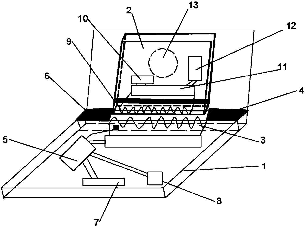
[0029] see figure 1 , in this embodiment, a wireless charging mobile phone and a mobile phone wireless charger, including a wireless charging mobile phone 2 and a wireless charger 1;
[0030] The wireless charging mobile phone includes a wireless charging interface 9 located at the bottom of the mobile phone, a magnetic shielding layer is arranged on the wireless charging interface, an electromagnetic receiving coil is arranged inside the wireless charging interface, and the two ends of the electromagnetic receiving coil are connected to the inside of the mobile phone body through the magnetic shielding layer The wireless charging receiving module 11, the wireless charging receiving module rectifies the electric energy received, voltage regulation and filtering supplies the mobile phone battery 12; the wireless charging mobile phone also includes a mobile phone charging control module 10 for regulating the work of the wireless charging receiving module state;
[0031] The wireless charger 1 also includes a charging notch 3 located on the top of the wireless charger for inserting a wireless charging mobile phone. An electromagnetic transmitting coil is arranged in the charging notch, and the two ends of the electromagnetic transmitting coil are connected to the middle part of the charger. A wireless charging transmitting module, a wireless charging transmitting detection module is arranged in the charging slot, which is used to detect whether the electromagnetic transmitting coil and the electromagnetic receiving coil start energy conversion and transmission, and the wireless charger also includes a microprocessor 5 and a low-power bluetooth module 7 , the microprocessor is used to collect the detection signal of the wireless charging transmission detection module and obtain the data information sent by the mobile phone received by the Bluetooth low power module connected to the wireless charging mobile phone Bluetooth, and according to the detection signal and data information to the wireless charging The charging transmitter module is controlled.
[0032]In this embodiment, a display screen 8 and an indicator light are provided on the lower side of the wireless charger. The indicator lights include three colors of red, yellow, and green, respectively indicating charging fault, charging completed, and charging in progress. These three working states; the display screen is used to display the charging data obtained after the bluetooth module of the wireless charging mobile phone is sent to the low power consumption bluetooth module and processed by the microprocessor, and the charging data includes the wireless charging The charged capacity of the phone and the charging time required to fully charge it.
[0033] In this embodiment, the outer side of the charging slot is also hinged with a support plate for supporting the wireless charging mobile phone inserted into the charging slot, and a position-adjustable support frame 13 is arranged in the middle of the support plate, and the support frame It is connected with the wireless charging mobile phone, and is used to support the wireless charging mobile phone when the wireless charging mobile phone is inserted into the charging slot, so as to prevent the mobile phone from vibrating or shifting by mistake.
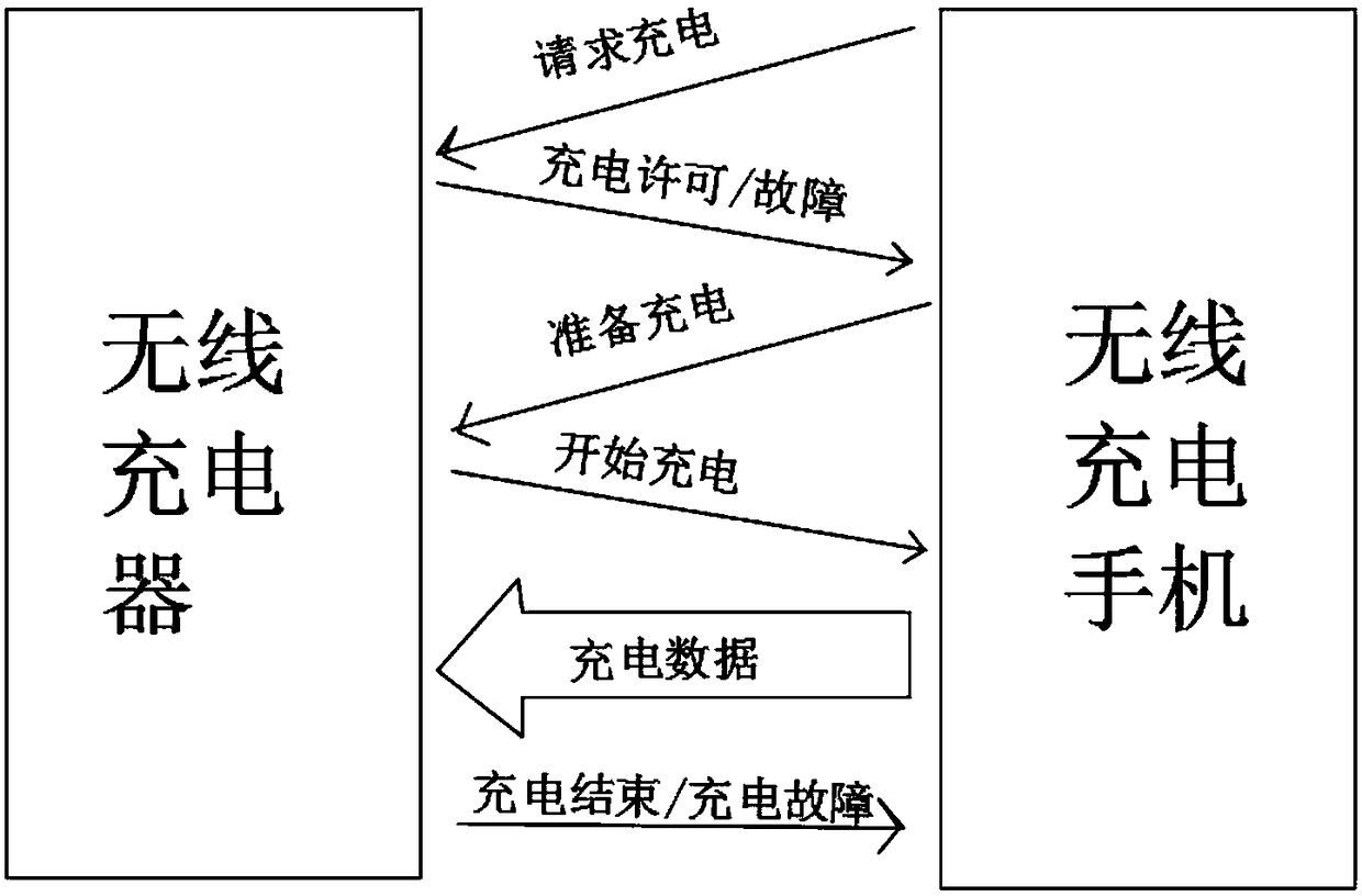
[0034] see figure 2 , in this embodiment, the charging slot of the wireless charger is provided with a magnetic shielding cover 4, and the upper left side of the magnetic shielding cover is provided with a two-dimensional code 6 corresponding to the wireless charger; After the charging mobile phone scans, the microprocessor receives the charging request signal sent by the wireless charging mobile phone, and starts to check whether there is historical fault information in the wireless charger. If it exists, it will alarm and display the fault; Described low-power bluetooth module; Described low-power bluetooth module 7 sends charging permission signal to the bluetooth module of described wireless charging mobile phone; And is controlled by microprocessor and opens magnetic shielding cover, exposes charging notch to facilitate wireless charging mobile phone to insert .
[0035] In this embodiment, the microprocessor includes a charging logic judging module, which is used to control the wireless charging transmitter module to quickly stop working and stop switching when the wireless charging mobile phone is not fully charged and is suddenly pulled away from the wireless charging mobile phone. Transmission of energy; it is also used to control the wireless charging transmitter module to start working after the Bluetooth low energy module receives the ready-to-charge signal sent by the mobile phone to charge the wireless charging mobile phone.
[0036] In this embodiment, after the wireless charging mobile phone receives the charging start signal sent by the wireless charger, it begins to sample the battery data at a fixed cycle, obtains charging data such as the capacity of the battery and the time required for full charging, and stores the charging data It is sent to the wireless charger and displayed on the display screen; when the battery of the mobile phone is fully charged, the wireless charger sends a signal of the end of charging to the wireless charging mobile phone, and controls the wireless charging transmitting module to stop working.
[0037] In this embodiment, when the wireless charging mobile phone is suddenly pulled away, the microprocessor immediately receives the alarm signal sent by the wireless charging transmission detection module, and generates an action to control the bypass switch module connected in parallel to the second voltage regulator signal, making the switch module work to bypass the second-stage voltage regulator.
[0038] Or when the power of the wireless charging mobile phone is full, the microprocessor receives the charging data and monitors the charging status of the mobile phone, and also generates an action signal to control the bypass switch module connected in parallel on the second voltage regulator, so that the switch module will work to the second voltage regulator. Secondary pressure regulation for bypass;
[0039] The bypass switch module can be used to reduce the input voltage of the inverter in the shortest time, thereby rapidly reducing the output power of the wireless charging system, so that the time required for shutdown is greatly reduced.
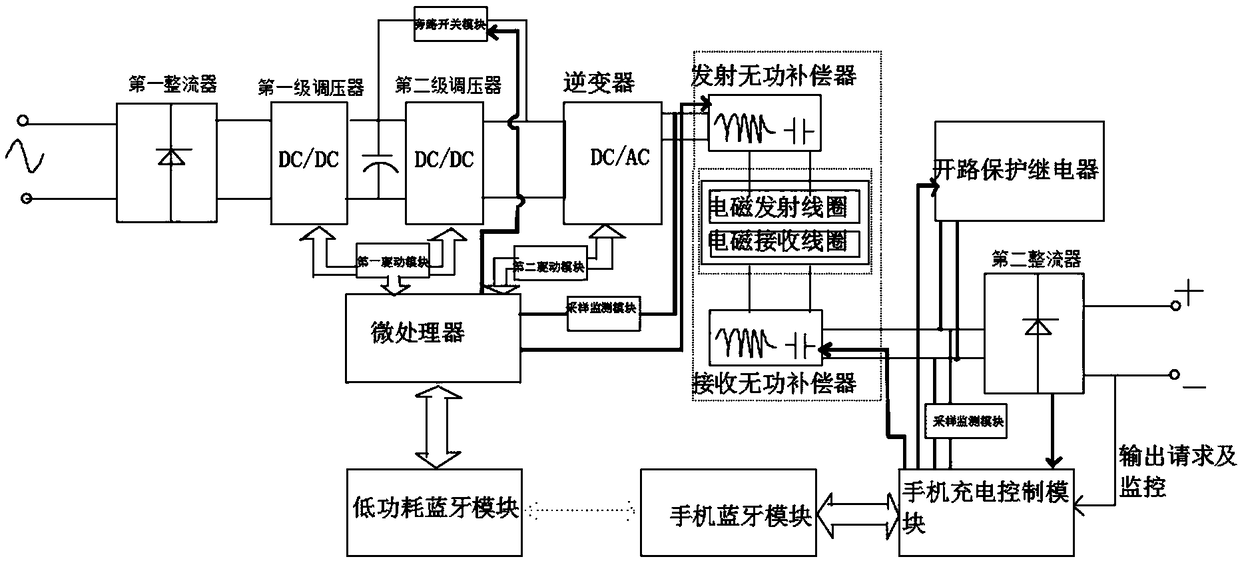
[0040] In this embodiment, the wireless charging transmitting module includes: a first rectifier connected in sequence, a first-stage voltage regulator, a second-stage voltage regulator, and a port connected in parallel between the first-stage voltage regulator and the second-stage voltage regulator The intermediate capacitor, the inverter, the transmitting reactive power compensator, and the first capacitor correspondingly matched with the inductance of the electromagnetic transmitting coil; the wireless charging receiving module includes a second capacitor connected in sequence correspondingly matched with the inductance of the electromagnetic receiving coil , Receiving reactive power compensator, second rectifier, voltage regulating filter;
[0041] The microprocessor controls the first-stage voltage regulation and the second-stage voltage regulation to adjust the voltage of the direct current output by the first rectifier to a target voltage; the inverter inverts the voltage-regulated direct current into Alternating current, after the alternating current passes through the transmitting reactive power compensator, it is transmitted through the electromagnetic transmitting coil, received by the electromagnetic receiving coil and transmitted to the receiving reactive power compensator; the mobile phone charging control module controls the second rectifier to rectify the alternating current After being converted into direct current, it is output to the energy storage battery of the mobile phone through voltage regulation and filtering;
[0042] The microprocessor is also used to obtain the maximum acceptable power of the mobile phone, the maximum acceptable power is determined by the existing electric capacity of the mobile phone, and is sent to the low-power Bluetooth module by the Bluetooth module of the mobile phone; the microprocessor A power threshold unit is included, and the power threshold unit calculates the maximum transmittable power of the wireless charger when the second-stage voltage regulator is not connected, and combines the maximum acceptable power of the mobile phone with the maximum transmittable power of the charger. The transmission power is compared, if the maximum transmittable power satisfies the maximum acceptable power of the mobile phone, the microprocessor controls the second voltage regulator to not work; if not, then controls the second voltage regulator to work on the inverter The input voltage of the device is adjusted.
[0043] In this embodiment, the calculation formula for the power threshold unit to calculate the maximum transmittable power of the wireless charger when the second-stage voltage regulator is not connected is:
[0044]
[0045] In the formula, p max is the maximum transmission power that can be transmitted, w 0 Set the charging resonant frequency for the wireless charger; L 1 is the inductance value corresponding to the electromagnetic transmitting coil; L 2 is the inductance value corresponding to the electromagnetic receiving coil; L s1 is the inductance value of the compensation inductor in the transmitting reactive power compensator; L s2 is the inductance value of the compensation inductance in the receiving reactive power compensator; h is the mutual inductance influence factor obtained from the test between the coil and the compensation inductance; k is the coupling coefficient between the inductance of the electromagnetic transmitting coil and the inductance of the electromagnetic receiving coil; V QIm is the maximum input voltage at the input terminal of the transmitting reactive power compensator when only the first-stage voltage regulator is used for voltage regulation; V CI The requested charging voltage for wireless charging phones.
[0046] In this embodiment, the wireless charger includes a power cord for connecting to an external commercial power supply, the first input terminal and the second input terminal of the first rectifier are connected to the commercial power supply, and the first output terminal of the first rectifier terminal and the second output terminal are respectively connected with the first input terminal and the second input terminal of the first-stage voltage regulator; the first output terminal and the second output terminal of the first-stage voltage regulator are respectively connected with the The first input end and the second input end of the second-stage voltage regulator are connected; one end of the intermediate capacitor is connected to the first output end of the first-stage voltage regulator, and the other end is connected to the second output end of the first-stage voltage regulator terminal; the first output terminal and the second output terminal of the second stage voltage regulator are respectively connected with the first input terminal and the second input terminal of the inverter; the first output terminal and the second output terminal of the inverter The output terminals are respectively connected to the first input terminal and the second input terminal of the transmitting reactive power compensator; the first output terminal and the second output terminal of the transmitting reactive power compensator are respectively connected to the first output terminal of the electromagnetic transmitting coil The input terminal is connected to the second input terminal;
[0047] The electromagnetic transmitting coil and the electromagnetic receiving coil are connected through electromagnetic coupling, and the first output end and the second output end of the electromagnetic receiving coil are respectively connected to the first input end and the second input end of the receiving reactive power compensator; The first output end and the second output end of the receiving reactive power compensator are respectively connected with the first input end and the second input end of the second rectifier; the first output end and the second output end of the second rectifier The terminals are respectively connected to the positive and negative poles of the mobile phone battery.
[0048] In this embodiment, the microprocessor is respectively connected to the controlled end of the first driving module and the controlled end of the second driving module; the first driving module respectively drives the first-stage voltage regulating and the second voltage regulator to adjust the working state; the second drive module is used to generate a trigger signal to drive the inverter to work; the control terminal of the mobile phone charging control module of the wireless charging mobile phone is respectively connected to the open circuit protection relay The controlled end of the rectifier and the controlled end of the second rectifier are connected.
[0049] In this embodiment, the first-stage voltage regulator is a buck-boost DC/DC converter; the second-stage voltage regulator is a Boost converter with a four-term interleaved PFC circuit topology.
[0050] In this embodiment, the mobile phone wireless charger and the wireless charging mobile phone respectively include a sampling monitoring module for sampling and monitoring voltage and current signals; the sampling monitoring module inside the mobile phone wireless charger is connected to a microprocessor; the wireless charging The sampling monitoring module of the mobile phone is connected to the charging control module of the mobile phone.
[0051] see Figure 4 , in this embodiment, the transmitting reactive power compensator is an LCC type reactive power compensation circuit, specifically: the first output terminal of the inverter is connected to the compensation inductor L s1 The input terminal; Compensation capacitor C s1 One end is connected with compensation inductance L s1 The output end of the inverter, the other end is connected to the second output end of the inverter; the first capacitor C 1 One end is connected to the compensation inductor L s1 The output end, the other end is connected to the electromagnetic transmitting coil L 1 The input terminal; the electromagnetic transmitting coil L 1 The output terminal of the inverter is connected to the second output terminal of the inverter; it can be seen that the first capacitor C 1 It is not only used as reactive power compensation, but also participates in the connection with the electromagnetic transmitting coil L 1 In the process of resonant pulsation; the receiving reactive power compensator is also an LCC type reactive power compensation circuit, the receiving reactive power compensator and the transmitting reactive power compensator are symmetrical in circuit structure, and the receiving reactive power compensator and the first Two capacitance C 2 It is not only used for reactive power compensation in the receiving reactive power compensator, but also used for harmonic resonance and energy conversion with the electromagnetic receiving coil.
[0052] In this embodiment, the inverter is a full bridge inverter.
[0053] In this embodiment, the microprocessor is used to control and adjust the charging state of the mobile phone when the mobile phone wireless charger is working, including correcting and adjusting the second capacitor on the side of the wireless charging mobile phone to ensure the full bridge of the mobile phone wireless charger. The inverter works in the zero-voltage switching state of the capacitor adjustment unit, and also includes a current adjustment unit for adjusting the output current of the receiving reactive power compensator to ensure that the wireless charger charges the wireless charging mobile phone at the maximum transmission efficiency.
[0054] In this embodiment, a plurality of adjusting capacitor branches are connected in parallel on both sides of the first capacitor and the second capacitor, and in this embodiment, two adjusting capacitor branches are set; the adjusting capacitor branches include Regulator capacitor C k And a controllable switch corresponding to the capacitor; by adjusting the switch of the controllable switch, the adjustment capacitor can be incorporated into both sides of the first capacitor or the second capacitor, wherein multiple adjustments on both sides of the first capacitor and the second capacitor The capacitor branch maintains a synchronous adjustment action, so that the correction and adjustment of the first capacitor or the second capacitor can be realized.
[0055] In this embodiment, the initial working state of the mobile phone wireless charging system is that the inverter works at the initial set frequency w 0 At this time, it is detected whether the MOSFET switch tube in the full-bridge inverter is working in the zero-voltage open state, and if so, it will continue to maintain this working state; if not, it will be adjusted through the capacitor adjustment unit, specifically: :
[0056] The capacitance adjustment unit obtains the actual input voltage of the transmitting reactive power compensator and the actual output voltage of the receiving reactive power compensator collected by the sampling monitoring module, and calculates its capacitance adjustment amount:
[0057]
[0058] In the formula, ΔC is the capacitance adjustment value, w 0 Set the resonant frequency for the wireless charging system to work; C 1 is the first capacitor; vQI is the actual input voltage at the input terminal of the transmitting reactive power compensator; v qo In order to receive the actual output voltage of the output terminal of the reactive power compensator; i zvs is the theoretical current value flowing through the corresponding switch tube when the MOSFET switch tube reaches zero voltage turn-off; γ is the design margin; k is the coupling coefficient between the electromagnetic transmitting coil and the electromagnetic receiving coil; L s1 is the compensation inductance of the transmitting reactive power compensator; L s2 is the compensation inductance of the receiving reactive power compensator; L 1 is the inductance of the electromagnetic transmitting coil; p max It is the maximum transmittable power of the wireless charger.
[0059] Control the controllable switch corresponding to the adjustment capacitor branch connected in parallel at both ends of the second capacitor according to the calculated capacitance adjustment amount; The controllable switch to realize the adjustment of the first capacitor and the second capacitor; after adjustment, the resonant frequency of the energy transmission between the electromagnetic transmitting coil and the electromagnetic receiving coil also produces a slight change. At this time, the microprocessor monitors the resonance frequency, and the operating frequency of the full-bridge inverter w 0 updated to the changed resonant frequency w g; and the second drive module drives the full-bridge inverter to work at an operating frequency of w g state.
[0060] In this preferred embodiment, in order to make the controllable switching tube of the inverter work under the working state of zero voltage on, through the improvement of the circuit structure and the establishment of a model of the circuit, a capacitance adjustment unit is designed to solve this problem, Through the calculation of the capacitance adjustment value, control the cut-in or cut-off of the adjustment capacitor branch, realize the adjustment of the first capacitor and the second capacitor, and then ensure that the MOSFET switch tube in the full-bridge inverter works in the zero-voltage open state, This reduces energy consumption.
[0061] In this embodiment, the battery of the wireless charging mobile phone is charged with a variable current charging method. With the change of the battery capacity of the mobile phone, when the battery power of the wireless charging mobile phone is low, a large current is used for constant current charging to realize fast charging. ; When the battery power of the wireless charging mobile phone is high, switch to low current constant current charging to realize floating charging.
[0062] In this embodiment, when the charging mode is switched over, the charging efficiency of the wireless charger will decrease, so the current regulation unit designs a circuit topology suitable for the charging mode by modeling the circuit topology of the wireless charger and the wireless charging mobile phone. The calculation formula of the charging efficiency of the wireless charger:
[0063]
[0064] In the formula, the η represents the charging efficiency of the wireless charger; R eq It is the equivalent resistance from the second rectifier and mobile phone battery load to the output terminal of the receiving reactive power compensator, which can be passed through Calculated, where v qo In order to receive the actual output voltage of the output terminal of the reactive power compensator; i Ls2 is the output current flowing through the output terminal of the receiving reactive power compensator; R 2 is the internal resistance of the electromagnetic receiving coil; k is the coupling coefficient between the electromagnetic transmitting coil and the electromagnetic receiving coil; Q 1 is the quality factor of the electromagnetic transmitting coil, where, R 1 is the internal resistance of the electromagnetic transmitting coil in the wireless charger, L 1 is the inductance of the electromagnetic transmitting coil; Q 2 is the quality factor of the electromagnetic receiving coil, L 2 is the inductance of the electromagnetic receiving coil; w c is the resonant frequency of the current flowing through the electromagnetic transmitting coil.
[0065] By analyzing and solving the extreme value of the calculation formula of the transmission efficiency, it can be obtained that the condition for the wireless charger to obtain the maximum transmission efficiency is that the output current at the output terminal of the receiving reactive power compensator reaches the current setting value, namely:
[0066]
[0067] Therefore, the wireless charger charges the wireless charging mobile phone. In order to obtain the maximum transmission efficiency, it is first necessary to collect and monitor the output current of the output terminal of the receiving reactive power compensator in real time through the sampling monitoring module on the mobile phone side, and the monitored output The current bluetooth is sent to the microprocessor, and the differential control conditioning circuit in the microprocessor obtains its differential mode by comparing the output current with the current set value, and generates a feedback signal after processing, and the second drive module receives the feedback signal pair The turn-on time of the switch tube in the full-bridge inverter is adjusted within a switching cycle, so that the output current value at the output terminal of the receiving reactive power compensator is close to the current set value. Through this adjustment, the wireless charger can keep the mobile phone charging. Work at higher transmission efficiency.
[0068] In this preferred embodiment, the circuit is modeled based on the equivalent principle of the circuit, the calculation formula of the transmission efficiency of the wireless charging system is analyzed and designed, and the conditions for the system to obtain the maximum transmission efficiency are determined according to the calculation formula of the transmission efficiency. The condition is to detect the output current of the output terminal of the corresponding secondary side reactive power compensator in the system, and perform feedback control in the primary side controller, so that the charging system is adjusted to the working state of the maximum transmission efficiency; through the above method, the adjustment speed is fast, The calculation amount is small, and the transmission efficiency of the charging system is improved.
[0069] In this preferred embodiment, under different working conditions of the charging system, the condition that the efficiency of the charger to charge the mobile phone is improved is designed. Feedback control is carried out in the microprocessor on the charger side, so that the charging system composed of the wireless charger and the charging mobile phone is adjusted to the working state of the maximum transmission efficiency; through the above method, the adjustment speed is fast, the calculation amount is small, and all Improvement of the transmission efficiency of the charging system described above.
[0070] In this preferred embodiment, a wireless charging mobile phone and a mobile phone wireless charger are designed. The control of the wireless charger is simple, and the communication is stable, and it is not easily disturbed by electromagnetic signals. The charging power of wireless charging is adjustable, and the charging efficiency is fast, the energy loss on the charger side is extremely small, and the energy conversion rate is high, which has good application value.
[0071] Finally, it should be noted that the above embodiments are only used to illustrate the technical solutions of the present invention, rather than limiting the protection scope of the present invention. Although the present invention has been described in detail with reference to the preferred embodiments, those of ordinary skill in the art should analyze , the technical solution of the present invention may be modified or equivalently replaced without departing from the spirit and scope of the technical solution of the present invention.

PUM

no PUM

Description & Claims & Application Information

We can also present the details of the Description, Claims and Application information to help users get a comprehensive understanding of the technical details of the patent, such as background art, summary of invention, brief description of drawings, description of embodiments, and other original content. On the other hand, users can also determine the specific scope of protection of the technology through the list of claims; as well as understand the changes in the life cycle of the technology with the presentation of the patent timeline. Login to view more.

Similar technology patents

Classification and recommendation of technical efficacy words

  • Simple control
  • Stable communication
Why Eureka
Try Eureka