
Modular rail system, rail system, mechanism and equipment for devices under test

A technology for testing devices and rails, which is applied to parts of electrical measuring instruments, electronic circuit testing, metal processing equipment, etc., to achieve the effect of simple adjustment of test performance

Active Publication Date: 2019-09-03
塞莱敦系统股份有限公司
View PDF8 Cites 0 Cited by
  • Summary
  • Abstract
  • Description
  • Claims
  • Application Information

AI Technical Summary

Problems solved by technology

Arms cover many parts of the wafer, limiting the number of sites that can be tested simultaneously

Method used


Image

  • Modular rail system, rail system, mechanism and equipment for devices under test
  • Modular rail system, rail system, mechanism and equipment for devices under test
  • Modular rail system, rail system, mechanism and equipment for devices under test

Examples


Embodiment Construction

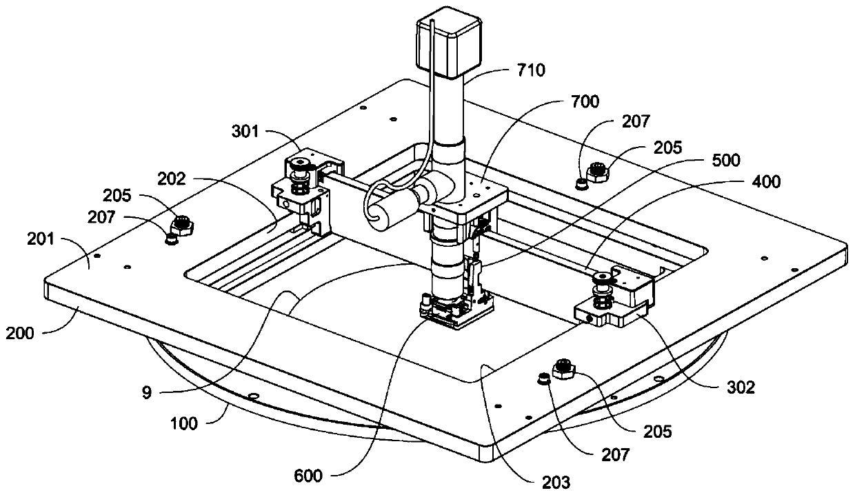
[0027] Embodiments disclosed herein relate generally to multi-site precision positioning mechanisms and, in particular, are directed to positioning a multi-probe array (e.g., across a wide Temperature range testing of semiconductor devices in semiconductor wafers).

[0028] Embodiments disclosed herein relate generally to systems, devices, and methods suitable for use in closed environments capable of controlling light, air, and / or electromagnetic interference. The test temperature of a DUT (eg, a wafer) can range from -65°C to 300°C and beyond. Some tests have measurements at multiple temperatures. The systems, devices and methods herein can be finely targeted to multiple sites and at desired temperatures and ranges. The systems, devices, and methods herein can provide a controlled environment to minimize thermal disturbances or effects that could misalign probe deflection (eg, when the system returns to thermal equilibrium).

[0029] The systems, devices, and methods here...


PUM


Abstract

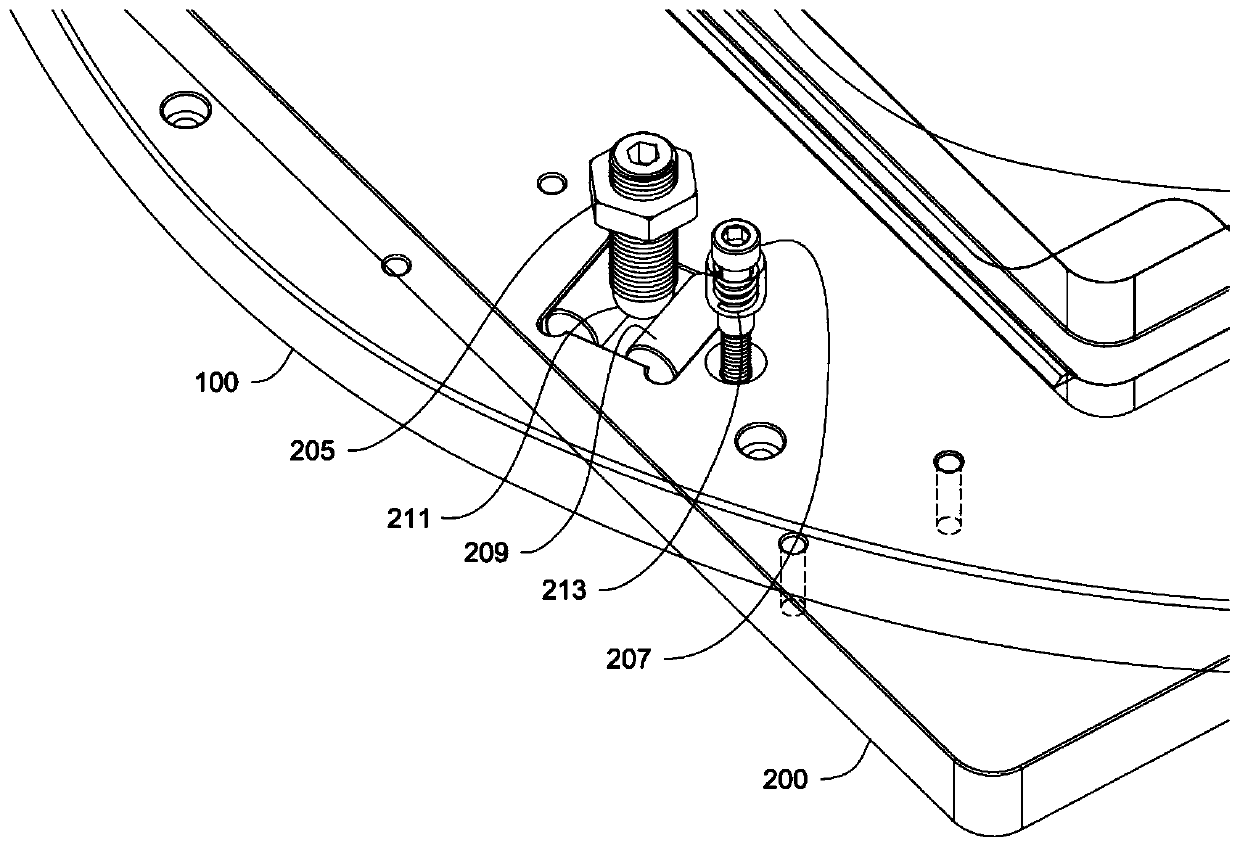
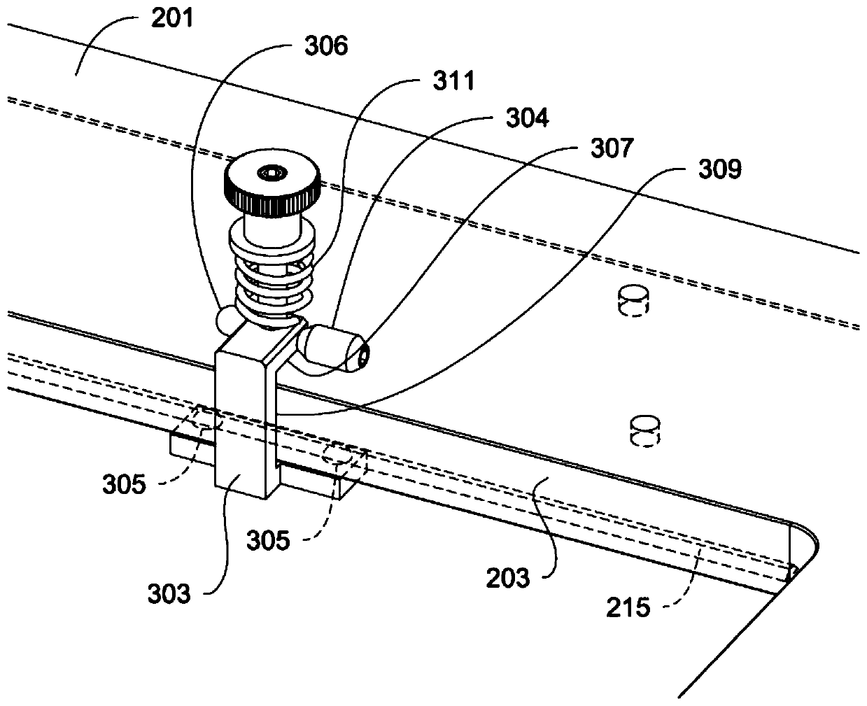
The systems, apparatus, and methods herein can provide a multi-site location mechanism suitable for testing device(s) under test ( DUT) (for example, semiconductor wafers) for long-term testing. The systems, devices, and methods herein include mounting components, mechanisms, and structures that provide excellent mechanical stability, allow for high-resolution optics at relatively close working distances, and enable Precise positioning is enabled at elevated temperatures in a controlled environment with minimal thermal disturbance. The systems, devices and methods herein can be modular, eg, modular to have rails and test sites that can be easily added or removed and that can allow access to probe modules in densely packed arrays.

Description

technical field [0001] The present disclosure relates generally to multi-site precision positioning mechanisms, and in particular, to positioning multi-probe arrays for devices under test (DUTs) (e.g., testing semiconductor devices in a semiconductor wafer across a wide temperature range) installation. Background technique [0002] Semiconductor circuit components are constantly getting smaller. Smaller processes will require larger test sample sizes and less stressful, longer-duration tests. [0003] With the advent of smaller devices there is also manufacturing pressure to reduce the size of the electrical contact pads. Smaller contact pads would require higher probe positioning accuracy in both XY and Z. Probe techniques designed for smaller pads may also have a smaller error margin in Z overtravel before they are damaged. The result may be small mechanical perturbations that would not be a problem with relatively large pads (e.g., 100µ0 or 200µ0 sized pads), but woul...

Claims


Application Information

Patent Timeline
Patent Type & Authority Patents(China)
IPC IPC(8): G01R31/28G01R1/067
CPCG01R1/07307G01R31/2601G01R31/28G01R31/2875G01R31/2891G01R31/2874G01R31/2887B23Q1/00
Inventor 约翰·L·戴克李威廉·A·芬克布莱恩·J·鲁特
Owner 塞莱敦系统股份有限公司
Learn More