Optical encoder with misalignment detection and adjustment method associated therewith
A technology for optical encoders and shaft measurement, applied in the field of optical encoders, can solve problems such as the detection of the amount of rotation that has not been proposed, and achieve the effect of easy adjustment
- Summary
- Abstract
- Description
- Claims
- Application Information
AI Technical Summary
Problems solved by technology
Method used
Image
Examples
no. 1 example
[0038] Next, an optical encoder according to a first embodiment of the present invention will be described in detail with reference to the drawings.
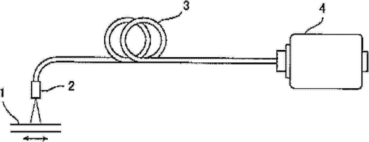
[0039] figure 1 is a view showing the optical encoder of the first embodiment of the present invention. The optical encoder of the first embodiment of the present invention includes: a scale 1 in which a reflection type diffraction grating is formed at a predetermined pitch in the measurement axis direction; and a probe 2 opposed to the surface of the scale 1 forming the diffraction grating through a predetermined gap, And it can move relative to the scale 1. The probe 2 is connected to a signal processing device 4 via a cable 3 .
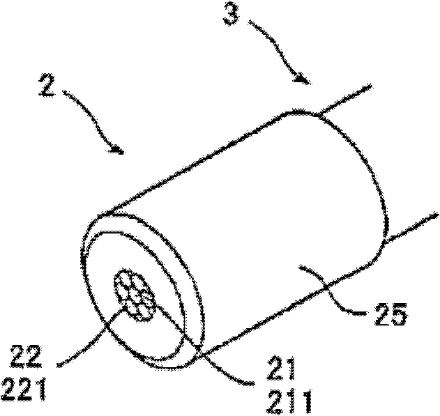
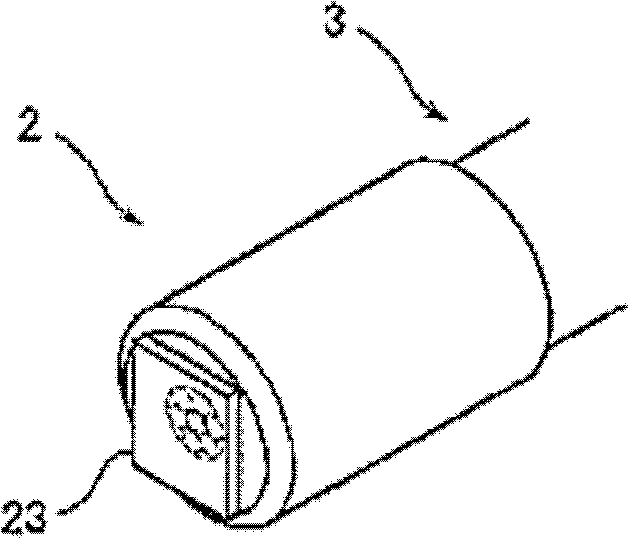
[0040] Figure 2A and 2B is a schematic diagram showing the probe 2 in the above optical encoder. In this embodiment, the cable 3 is constituted by bundling a plurality of optical fibers together. The cable 3 is constituted by bundling together six receiving optical fibers 221 around the light ...
no. 2 example
[0073] In the first embodiment, the Lissajous radius R of the quadrature differential signal A, B or the square value of the radius R 2 Serves as attitude monitoring signal MY for yaw direction. For example, in the second embodiment, the Lissajous radius R is approximated to the characteristic function, and the inverse or differential function of the characteristic function is used. This can improve adjustment resolution.
[0074] For example, if Figure 10 As shown, the relationship between the rotation angle and the size of the Lissajous radius can be approximated by Gaussian. Therefore, when using the logarithm of the inverse function, the adjustment resolution in the region of the yaw rotation angle in the vicinity of 0.0° (near the best alignment) is improved.
[0075] Therefore, if Figure 11 As shown, an inverse function conversion block 79 that performs an inverse function conversion on the Lissajous radius R is arranged in the AGC / yaw detection circuit 70, and the...
no. 3 example
[0085] Figure 13 It is a diagram showing an example in which arithmetic processing is realized by software using a microcomputer or a PC.
[0086] That is, the signal processing device 4 includes an A / D conversion unit 80 and a calculation circuit 90 instead of the phase detection circuit 40 , pitch detection circuit 60 , roll detection circuit 50 and AGC / yaw detection circuit 70 . The calculation circuit 90 is connected to the external PC 10 .
[0087] The A / D conversion unit 80 converts the phase signals Sa, Sab, Sb, Sbb, and attitude monitor signals Sz, Szb into digital signals, and supplies the digital signals to the calculation circuit 90 . The calculating circuit 90 calculates the quadrature difference signals A, B, the attitude monitor signals MP, MR, the normalized quadrature difference signals VA, VB, the Lissajous radius R, etc. from the phase signal and the attitude monitor signal converted into digital signals, and provide them to PC 10 . Alternatively, the pha...
PUM
 Abstract
Description
Claims
Application Information
 - R&D
- Intellectual Property
- Life Sciences
- Materials
- Tech Scout
- Unparalleled Data Quality
- Higher Quality Content
- 60% Fewer Hallucinations
Browse by: Latest US Patents, China's latest patents, Technical Efficacy Thesaurus, Application Domain, Technology Topic, Popular Technical Reports.
© 2025 PatSnap. All rights reserved.Legal|Privacy policy|Modern Slavery Act Transparency Statement|Sitemap|About US| Contact US: help@patsnap.com


