Clamping method for machining

A technology of mechanical processing and clamping device, which is applied in metal processing, metal processing equipment, metal processing machinery parts, etc., can solve problems such as single function, low processing efficiency, troublesome staff, etc., and achieve strong flexibility and strong practicability , high processing efficiency

Inactive Publication Date: 2018-11-13
CHUZHOU KEXIN MECHANICAL TECH
View PDF6 Cites 5 Cited by
  • Summary
  • Abstract
  • Description
  • Claims
  • Application Information

AI Technical Summary

Problems solved by technology

[0002] In the process of machining, it is often necessary to clamp and fix the plate-shaped workpiece to prevent the workpiece from moving and affecting the processing effect
The traditional clamping device can only simply clamp the workpiece, and its function is relatively single. Since the clamping device is usually fixed, it can only process the same part of the workpiece surface during processing. When other parts need to be processed, It is necessary to adjust the workpiece, which is time-consuming and labor-intensive, and the processing efficiency is low, which brings great trouble to the staff. For this reason, we propose a clamping method for machining

Method used


Image

  • Clamping method for machining
  • Clamping method for machining
  • Clamping method for machining

Examples


Embodiment Construction

[0014] The following will clearly and completely describe the technical solutions in the embodiments of the present invention with reference to the accompanying drawings in the embodiments of the present invention. Obviously, the described embodiments are only some, not all, embodiments of the present invention.

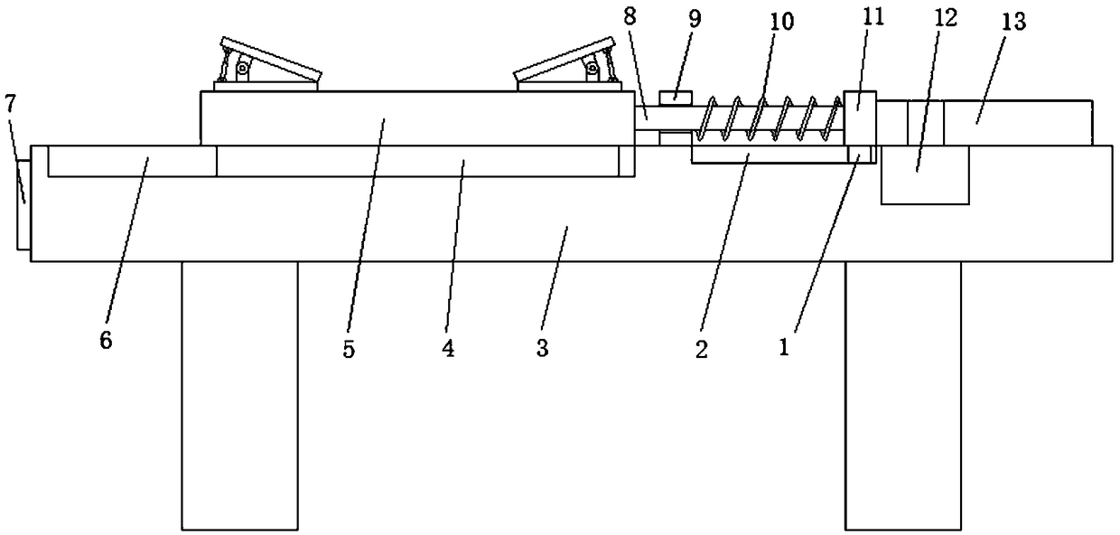
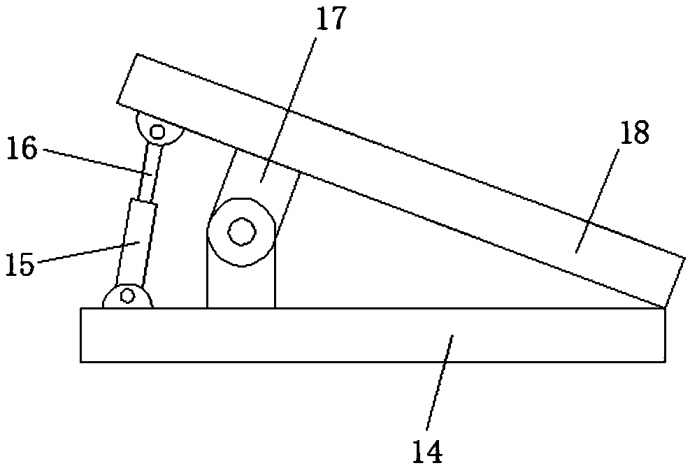
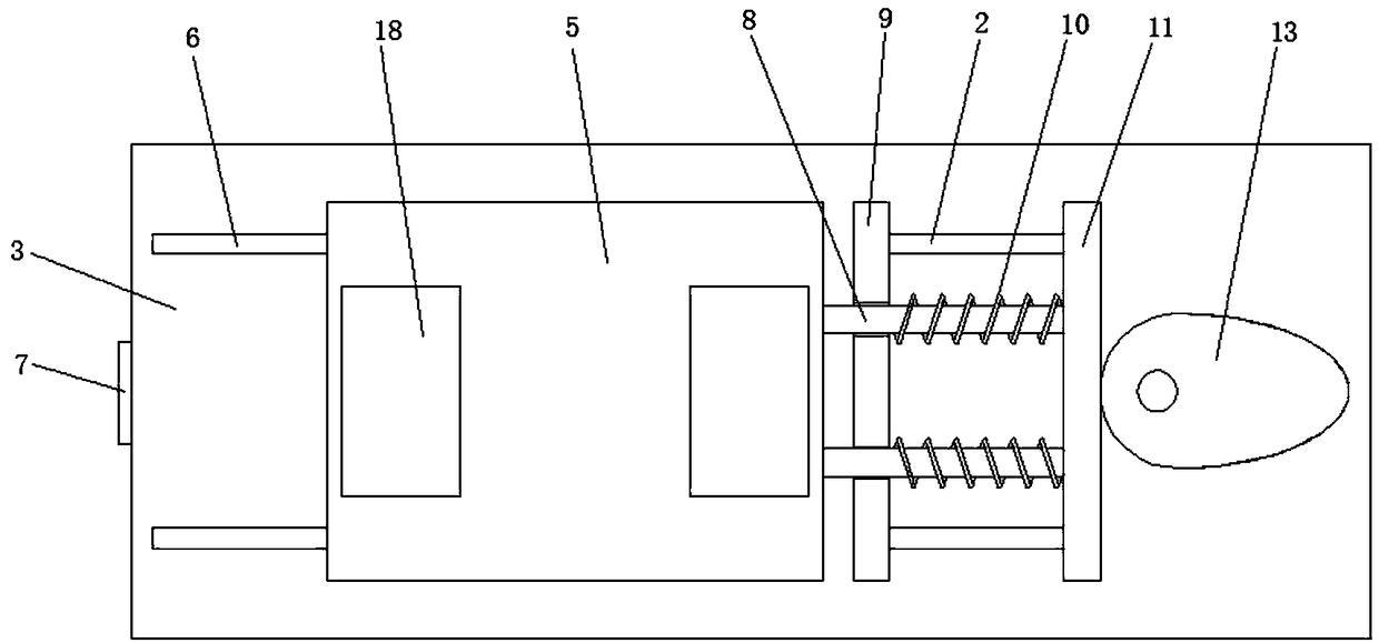
[0015] refer to Figure 1-3 , a clamping device for mechanical processing, comprising a horizontally arranged workbench 3, one side of the top of the workbench 3 is slidably connected with a horizontally arranged movable plate 5, and both sides of the top of the movable plate 5 are fixed with horizontally arranged fixed splints 14. A movable splint 18 is provided above the fixed splint 14, and a hinge 17 is provided on the side where the fixed splint 14 and the movable splint 18 are close to each other. , the top of the fixed splint 14 is hinged with two cylinders 15 away from each other near the side of the hinge 17, the output shaft of the cylinder 15 is connected ...


PUM


Abstract

The invention discloses a clamping method for machining. The clamping method for machining is used and comprises a horizontally-arranged working table, a horizontally-arranged movable plate is connected to one side of the top end of the working table in a sliding manner, horizontally-arranged fixed clamping plates are fixed to the two sides of the top end of the movable plate, movable clamping plates are arranged above the fixed clamping plates, hinges are arranged on the sides, getting close to each other, of the fixed clamping plates and the movable clamping plates, the two hinges are far away from each other, the fixed clamping plates and the movable clamping plates are rotationally connected through the hinges, two air cylinders being far away from each other are hinged to the sides, getting close to the hinges, of the top ends of the fixed clamping plates, stretchable rods are connected to output shafts of the air cylinders, the top ends of the stretchable rods are hinged to the movable clamping plates, and a driving motor is embedded into the side, being far away from the movable plate, of the top end of the working table. The clamping method has the advantages that workpieces can be driven to move back and forth according to needs, the surfaces of the workpieces only need to be subjected to one-time machining, the workpieces do not need to be adjusted, time and labor aresaved, and the machining efficiency is high.

Description

technical field [0001] The invention relates to the technical field of machining, in particular to a clamping method for machining. Background technique [0002] During the machining process, it is often necessary to clamp and fix the plate-shaped workpiece to prevent the workpiece from moving and affect the processing effect. The traditional clamping device can only simply clamp the workpiece, and its function is relatively single. Since the clamping device is usually fixed, it can only process the same part of the workpiece surface during processing. When other parts need to be processed, Then the workpiece needs to be adjusted, which is time-consuming and labor-intensive, and the processing efficiency is low, which brings great trouble to the staff. For this reason, we propose a clamping method for machining. Contents of the invention [0003] The object of the present invention is to propose a clamping method for machining in order to solve the shortcomings in the pri...

Claims


Application Information

Patent Timeline
Patent Type & Authority Applications(China)
IPC IPC(8): B23Q3/08B23Q7/00
Inventor 吴孝奎李明防李宣春
Owner CHUZHOU KEXIN MECHANICAL TECH
Why Eureka
Try Eureka