
Transmission device for material cutting machine

A technology of transmission device and cutting machine, which is applied in the direction of metal processing machinery parts, maintenance and safety accessories, metal processing, etc. It can solve the problems of complex structure, no collection of cutting waste, etc., and achieve the effect of avoiding scattering

Pending Publication Date: 2018-11-13
XINXIANG ZHEN YING MACHINERY EQUIP CO LTD
View PDF3 Cites 0 Cited by
  • Summary
  • Abstract
  • Description
  • Claims
  • Application Information

AI Technical Summary

Problems solved by technology

[0007] Aiming at the deficiencies of the prior art, the present invention provides a transmission device for a material cutting machine, which solves the problems of not collecting cutting waste and having a complicated structure

Method used


Image

  • Transmission device for material cutting machine
  • Transmission device for material cutting machine
  • Transmission device for material cutting machine

Examples


Embodiment Construction

[0021] The following will clearly and completely describe the technical solutions in the embodiments of the present invention with reference to the accompanying drawings in the embodiments of the present invention. Obviously, the described embodiments are only some, not all, embodiments of the present invention. Based on the embodiments of the present invention, all other embodiments obtained by persons of ordinary skill in the art without making creative efforts belong to the protection scope of the present invention.

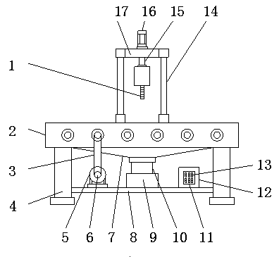
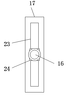
[0022] Such as Figure 1-3 As shown, the present invention provides a technical solution: a transmission device for a material cutting machine, including an installation frame 2, legs 4 are installed at the bottom of the installation frame 2, support plates 8 are installed between the legs 4, support plates 8 A motor 5 is installed on the top of the motor 5, a belt pulley 6 is installed on the output end of the motor 5, a guide hopper 7 is installed on the bot...


PUM


Abstract

The invention discloses a transmission device for a material cutting machine. The transmission device comprises a mounting frame. A motor is mounted at the top of a support plate; a belt pulley is mounted at the output end of the motor; a material guiding hopper is mounted at the bottom of the mounting frame; a material collecting groove is mounted at the top of the support plate on one side of the motor; the bottom of the material guiding hopper is connected with the material collecting groove through a material guiding pipe; a first roller and a second roller are mounted in the mounting frame; a driving wheel is mounted at one end of each of the first roller and the second roller; a driven wheel is mounted at the other end of each of the first roller and the second roller; the driven wheel mounted at one end of the first roller is connected with the driven wheel mounted at one end of the second roller through a second belt; and the output end of the belt pulley is connected with thedriving wheel at other end of the first roller through a first belt. Through arranging the motor, the first roller, the second roller and the material collecting groove, the transmission device solvesthe problems that cut sweeps cannot be collected and the structure is complicated.

Description

technical field [0001] The invention relates to the technical field of cutting devices, in particular to a transmission device for a material cutting machine. Background technique [0002] With the development of the modern mechanical processing industry, the requirements for cutting quality and precision are constantly improving, and the requirements for improving production efficiency, reducing production costs, and highly intelligent automatic cutting functions are also increasing. The development of CNC cutting machines must adapt to the requirements of the development of modern machining industry. Cutting machine is divided into flame cutting machine, plasma cutting machine, laser cutting machine, water cutting and so on. The laser cutting machine has the fastest efficiency, the highest cutting precision, and the cutting thickness is generally small. The cutting speed of the plasma cutting machine is also very fast, and the cutting surface has a certain slope. The fl...

Claims


Application Information

Patent Timeline
Patent Type & Authority Applications(China)
IPC IPC(8): B23Q7/05B23Q11/00
CPCB23Q7/055B23Q11/0067
Inventor 孟保亮秦英王云利秦新波
Owner XINXIANG ZHEN YING MACHINERY EQUIP CO LTD
Learn More