
Unloading device

A technology of blanking and loading plate, which is applied in the direction of metal processing, etc., can solve the problems of inability to limit the position of the pipe, and cannot realize the automatic separation of waste materials, so as to improve the cutting accuracy and realize the effect of automatic separation

Active Publication Date: 2020-08-28
HANS LASER TECH IND GRP CO LTD +1
View PDF5 Cites 0 Cited by
  • Summary
  • Abstract
  • Description
  • Claims
  • Application Information

AI Technical Summary

Problems solved by technology

[0004] The technical solution disclosed in the present invention can at least solve the following technical problems: the pipe material unloading device in the prior art cannot limit the position of the pipe material, and cannot realize automatic separation of waste materials

Method used


Image

  • Unloading device
  • Unloading device
  • Unloading device

Examples


Embodiment Construction

[0046] In order to facilitate the understanding of the present invention, the present invention will be described more fully below with reference to the associated drawings. Preferred embodiments of the invention are shown in the accompanying drawings. However, the present invention can be embodied in many different forms and is not limited to the embodiments described herein. On the contrary, these embodiments are provided to make the understanding of the disclosure of the present invention more thorough and comprehensive.

[0047] Unless otherwise defined, all technical and scientific terms used herein have the same meaning as commonly understood by one of ordinary skill in the technical field of the invention. The terms used herein in the description of the present invention are for the purpose of describing specific embodiments only, and are not intended to limit the present invention. The terms "first", "second", "third" and the like in the claims, description and drawi...


PUM


Abstract

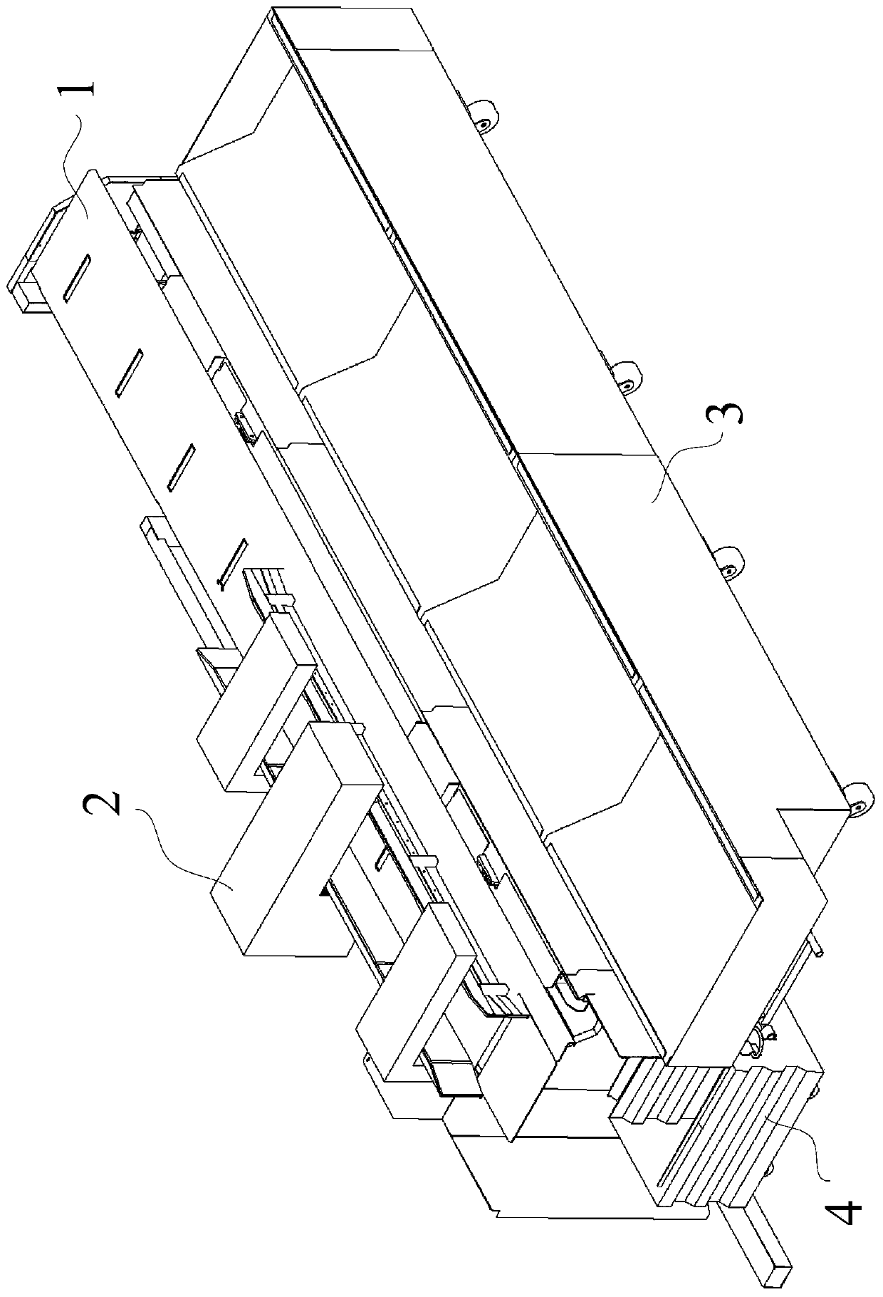
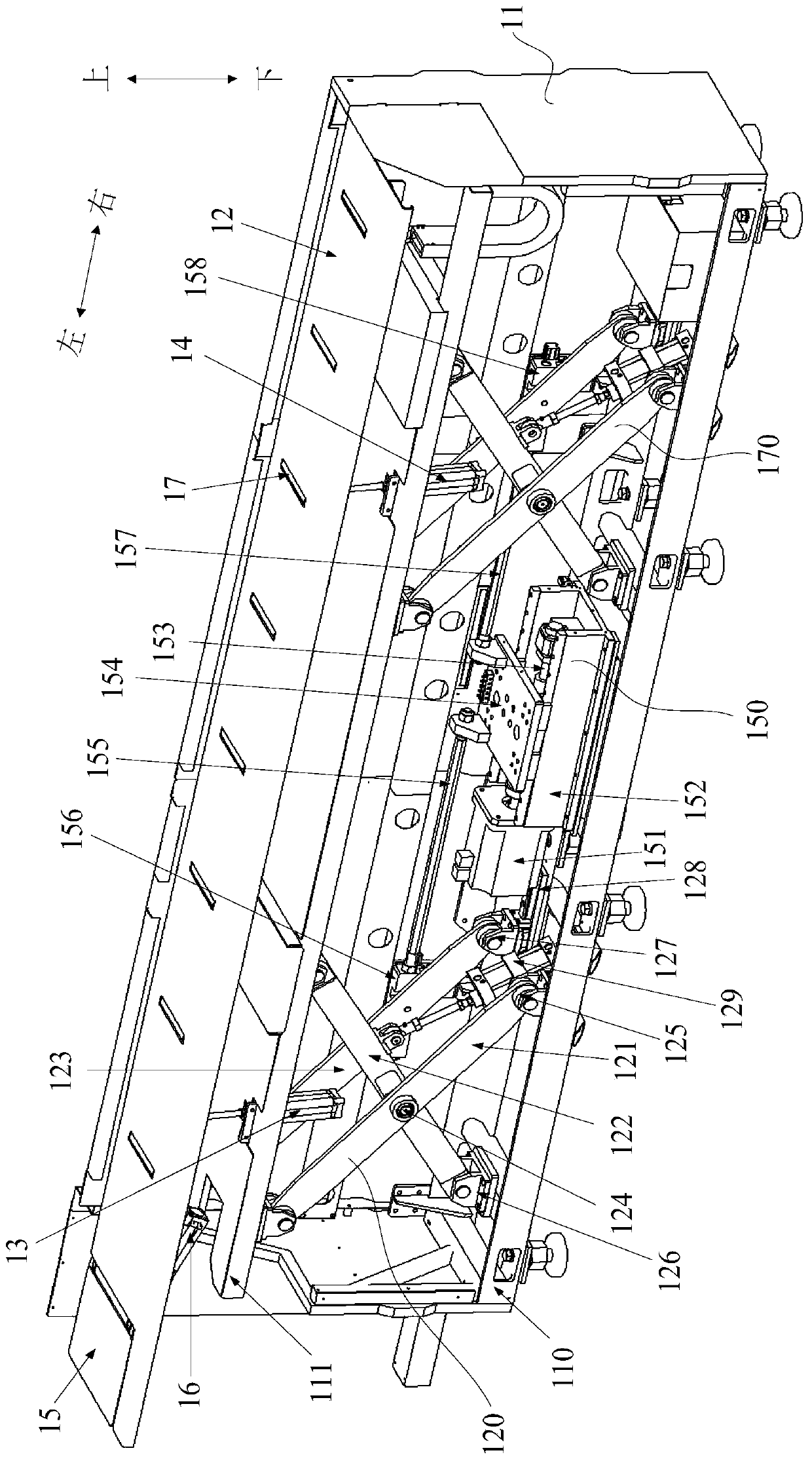
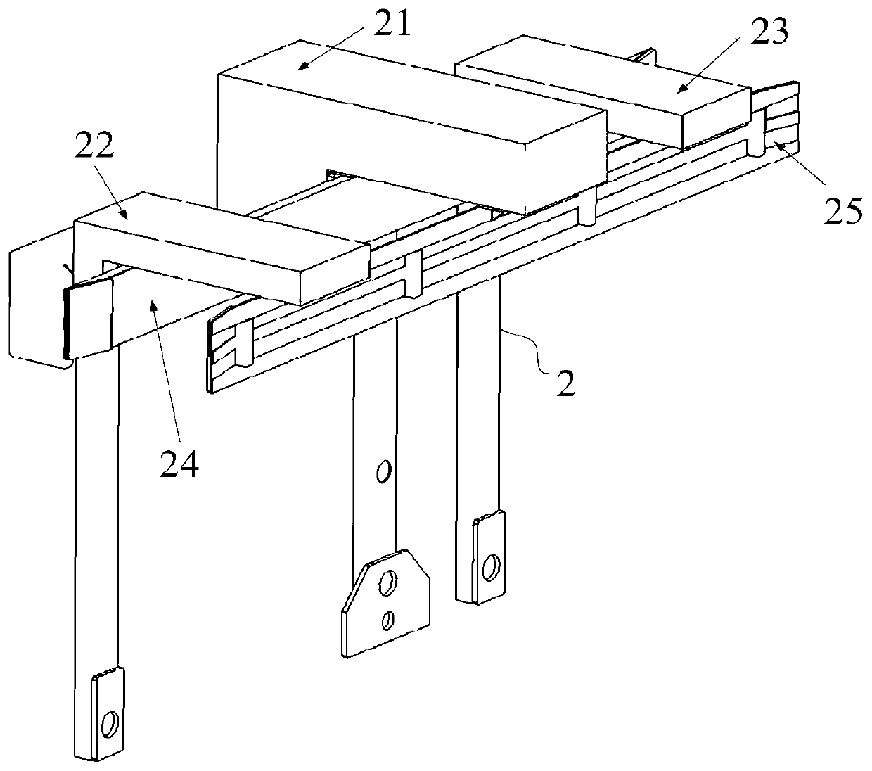
The embodiment of the invention discloses an unloading device, and relates to the technical field of mechanical automation. The unloading device comprises an unloading part and a limiting part. The unloading device comprises a shear-fork type lifting platform, a loading plate, a first air cylinder, a second air cylinder, a turnover plate and a third air cylinder. The shear-fork type lifting platform comprises a machine frame, a bracket, a first shear-fork type lifting mechanism, a travel control mechanism and a second shear-fork type lifting mechanism. The limiting part comprises a first limiting mechanism, a second limiting mechanism, a third limiting mechanism, a first striker plate and a second striker plate. The unloading device is helpful to improve the cutting accuracy of pipe product and realize the automatic separation of waste materials.

Description

technical field [0001] The technical solutions disclosed in the embodiments of the present invention relate to the technical field of mechanical automation, and in particular to the unloading device. Background technique [0002] At present, in the cutting process of pipes, feeding devices and unloading devices have been widely used to realize automatic feeding and unloading of pipes. [0003] In the process of studying the present invention, the inventor found that the cutting device for the pipe material in the prior art cannot limit the position of the pipe material, thus affecting the cutting accuracy of the pipe material. In addition, the pipe material unloading device in the prior art cannot realize the automatic separation of waste materials. Contents of the invention [0004] The technical solution disclosed in the present invention can at least solve the following technical problems: the pipe material unloading device in the prior art cannot limit the position of...

Claims


Application Information

Patent Timeline
Patent Type & Authority Patents(China)
IPC IPC(8): B26D7/02B26D7/18B26D7/32B26D7/22
CPCB26D7/02B26D7/18B26D7/22B26D7/32
Inventor 叶仁平胡柱罗贵长夏小川陈焱陈根余赵剑高云峰
Owner HANS LASER TECH IND GRP CO LTD
Learn More