A cutting workbench equipped with a workpiece fastening mechanism for mechanical manufacturing

A fastening mechanism and mechanical manufacturing technology, which is applied in the direction of manufacturing tools, metal processing machinery parts, maintenance and safety accessories, etc., can solve the problems of potential safety hazards, vibration at both ends of hollow metal circular tubes, poor fixing effect of hollow metal circular tubes, etc. , to achieve accurate cutting effect

Active Publication Date: 2020-07-03
徐州富能机械有限公司
View PDF2 Cites 0 Cited by
  • Summary
  • Abstract
  • Description
  • Claims
  • Application Information

AI Technical Summary

Problems solved by technology

[0007] In order to solve the above-mentioned technical problems, the present invention provides a cutting workbench equipped with a workpiece fastening mechanism for mechanical manufacturing, so as to solve the existing similar devices. Poor, when the device is cutting, the two ends of the hollow metal tube are likely to vibrate due to cutting, which affects the cutting accuracy of the device; and the collection and cooling effect of the high-temperature metal powder generated by cutting is poor, and the high-temperature metal powder is easy to splash on people or combustibles above, causing safety hazards

Method used


Image

  • A cutting workbench equipped with a workpiece fastening mechanism for mechanical manufacturing
  • A cutting workbench equipped with a workpiece fastening mechanism for mechanical manufacturing
  • A cutting workbench equipped with a workpiece fastening mechanism for mechanical manufacturing

Examples


Embodiment

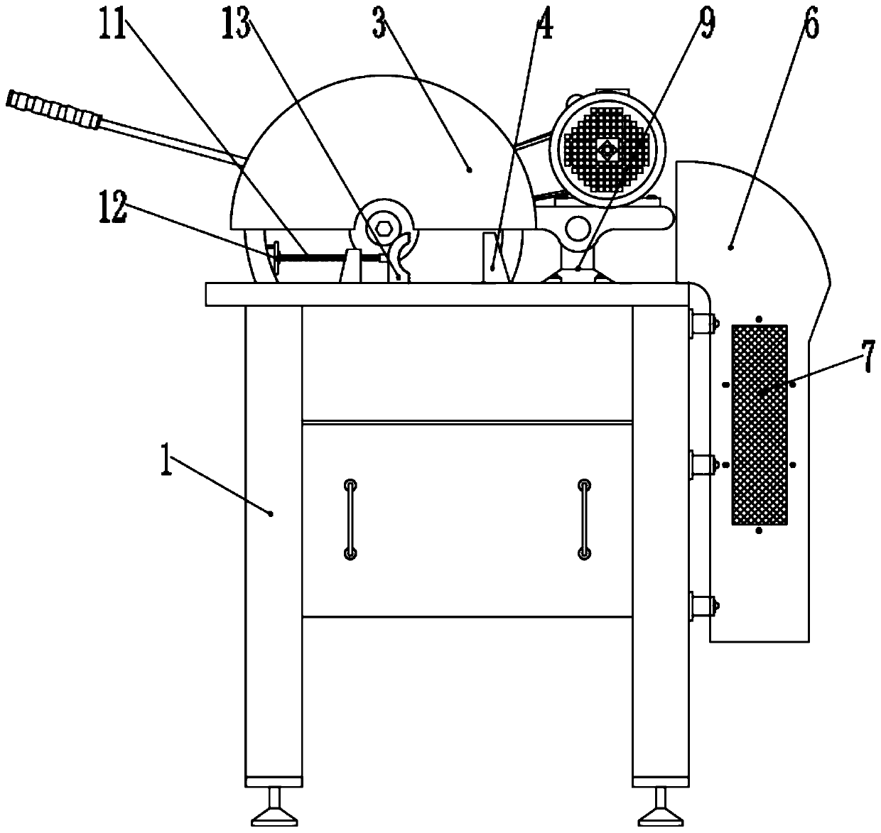
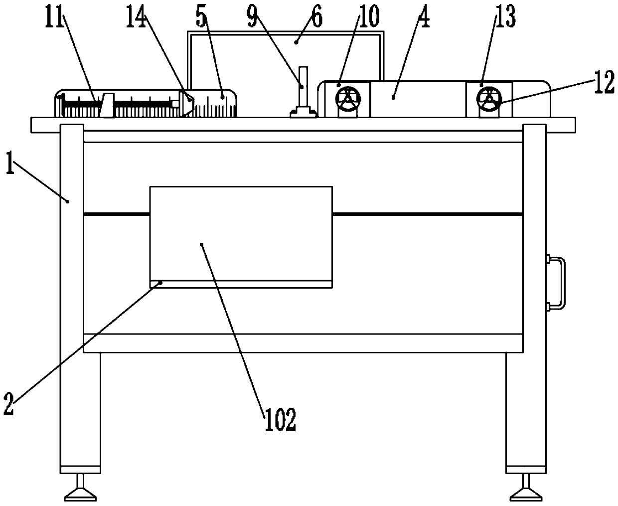
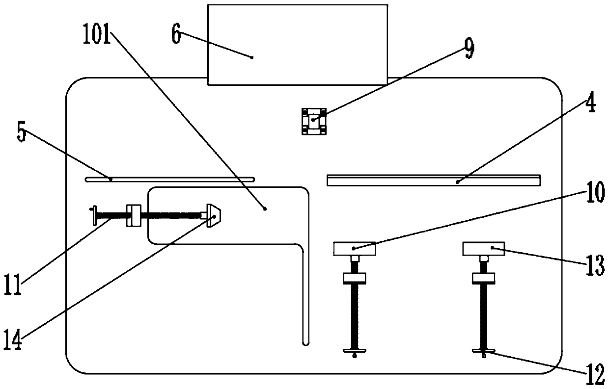
[0037] as attached figure 1 to attach Figure 10 Shown:

[0038]The invention provides a cutting workbench equipped with a workpiece fastening mechanism for mechanical manufacturing, comprising a cutting table 1, a blanking port 101, a blanking chamber 102, a buffer rubber pad 2, a cutting tool 3, a fixing bar 4, and a fixing bar ruler 5. Iron slag collection box 6, exhaust net 7, cooling fluid 8, tool support frame 9, No. 1 fixed block 10, No. 1 fixed slot 1001, threaded shaft 11, turning handle 12, No. 2 fixed block 13 , No. 2 fixed slot 1301, fixed chuck 14 and briquetting block 15; a blanking cavity 102 is provided inside the left end of the cutting table 1, and the outlet of the blanking cavity 102 is located on the front end of the cutting table 1; The support frame 9 is mounted on the middle part of the top end face of the cutting table 1 by screws, and the cutting tool 3 is rotatably connected to the tool support frame 9, and the bottom of the cutting tool 3 is locat...


PUM


Abstract

The invention provides a cutting workbench provided with workpiece fastening device for machine manufacturing. The cutting workbench comprises a fixing chuck and a pressing block. A blanking cavity isformed in the left end of the cutting workbench, and an outlet of the blanking cavity is located on the front end face of the cutting workbench. A tool supporting frame is installed on the middle portion of the top end face of the cutting workbench through screws, a cutting tool is rotatably connected to the tool supporting frame, and the bottom of the cutting tool is located in a blanking opening. A fixing strip is installed on the right end of the top end face of the cutting workbench, and a fixing narrow scale is installed on the left end of the top end face of the cutting workbench. The centralized collection of high-speed high-temperature metal particles cut off by the cutting workbench is facilitated, and high-temperature powder is prevented from bursting against the surrounding personnel to cause harm to the personnel. Cooling liquid in a slag collection box is arranged, the high-temperature powder collected in the slag collection box cam be cooled, and high temperature metal particles are prevented from igniting the surrounding combustible to cause potential safety hazards.

Description

technical field [0001] The invention belongs to the technical field of mechanical manufacturing, and more specifically relates to a cutting workbench equipped with a workpiece fastening mechanism for mechanical manufacturing. Background technique [0002] With the advancement of science and technology, the field of machinery manufacturing is also booming, and most of the machinery will use hollow metal round tubes (or square tubes) to support and fix various parts inside the machinery to reduce the weight of the machinery itself; but the machinery The lengths and specifications of the hollow metal circular tubes used in the manufacture are different, requiring the staff to carry out quantitative cutting and manufacturing according to the type of use and specifications, and this process basically uses a professional cutting workbench for manufacturing. [0003] Based on the above, the inventor found through retrieval that existing similar devices, such as a circular knife cut...

Claims


Application Information

Patent Timeline
Patent Type & Authority Patents(China)
IPC IPC(8): B23D19/00B23D33/04B23Q11/00B23Q17/20B21D43/20
CPCB21D43/20B23D19/00B23D33/04B23Q11/0042B23Q17/20
Inventor 王晴徐亚伟
Owner 徐州富能机械有限公司
Why Eureka
Try Eureka