Supercharge Your Innovation With Domain-Expert AI Agents!

Infrared hot riveting machine

A technology of infrared heat and riveting machine, which is applied in the field of processing technology, can solve the problems of low work efficiency, achieve the effect of improving heating efficiency and solving the effect of slow heating

Active Publication Date: 2018-11-13
CHONGQING TECH & BUSINESS UNIV
View PDF10 Cites 0 Cited by
  • Summary
  • Abstract
  • Description
  • Claims
  • Application Information

AI Technical Summary

Problems solved by technology

[0005] This application provides an infrared hot riveting machine to solve the problem of low working efficiency of existing infrared hot riveting machines

Method used


Image

  • Infrared hot riveting machine
  • Infrared hot riveting machine
  • Infrared hot riveting machine

Examples


Embodiment Construction

[0024] The following will clearly and completely describe the technical solutions in the embodiments with reference to the drawings in the embodiments of the application. Obviously, the described embodiments are only some of the embodiments of the application, not all of them. Based on the embodiments in this application, all other embodiments obtained by persons of ordinary skill in the art without making creative efforts belong to the scope of protection of this application.

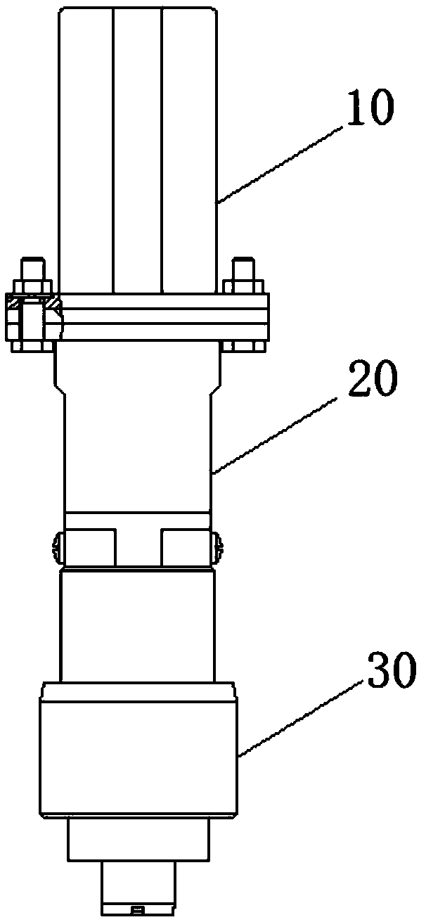
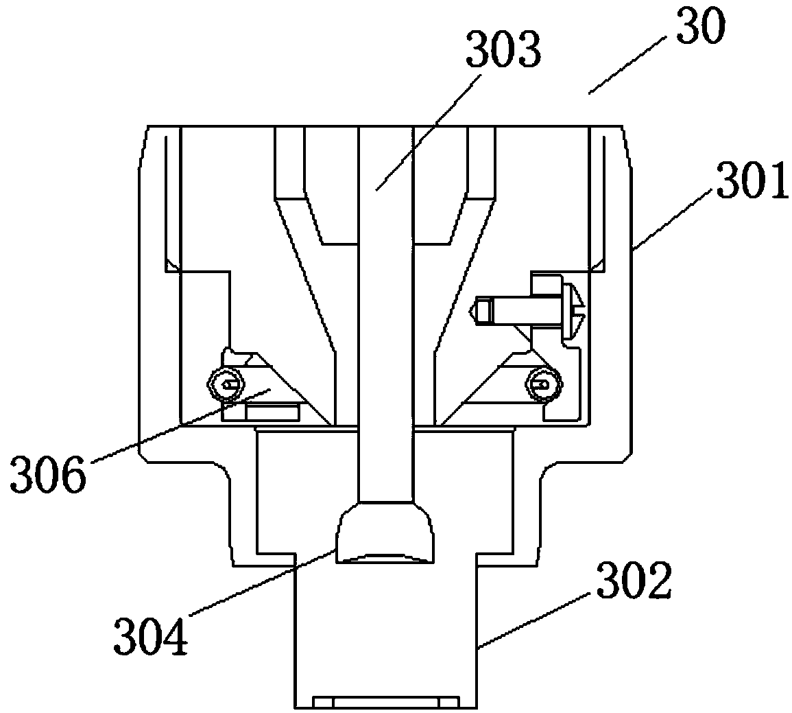
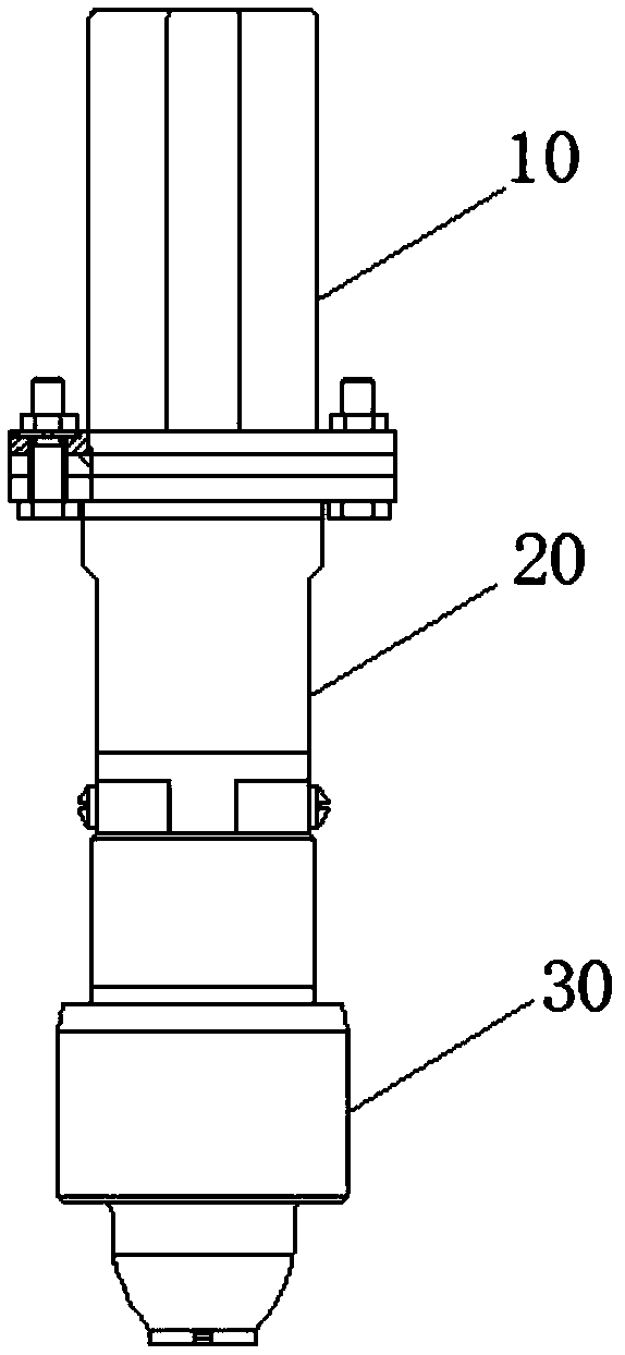
[0025] The embodiment of the present application provides an infrared hot riveting machine, refer to image 3 , showing a schematic structural view of an infrared hot riveting machine provided by the present application, see Figure 4 , shows a schematic structural view of a riveting head in an infrared thermal riveting machine provided by the present application. The infrared hot riveting machine provided in the embodiment of the present application includes: a cylinder 10, a connecting piece 20 and ...


PUM

PropertyMeasurementUnit
reflectanceaaaaaaaaaa

Abstract

The invention provides an infrared hot riveting machine. The infrared hot riveting machine comprises an air cylinder, a connecting part and a riveting head. The riveting head comprises a connecting body. A reflector, an infrared heating tube, a first blowing channel and a second blowing channel are arranged in the connecting body, the infrared heating tube is fixed to the bottom of the connectingbody, the reflector is arranged on the top of the infrared heating tube, both the first blowing channel and the second blowing channel communicate to a riveting cavity, and a reflective hood and a vent hole are formed in the riveting cavity. By arranging the reflector on the top of the infrared heating tube and arranging the reflective hood in the riveting cavity, high strength infrared radiationgenerated by the infrared heating tube can be reflected to a plastic joint, so that the plastic joint is quickly heated to be melted, and meanwhile, during heating, air is blown to the riveting cavitythrough the first blowing channel, so that air convection is generated in the riveting cavity to transfer heat, and therefore, the heating efficiency of the infrared heating tube is improved, and theproblem that the work efficiency of the infrared riveting machine is affected as the plastic joint of an existing infrared riveting machine is heated relatively slowly and is relatively large in heatloss is solved.

Description

technical field [0001] The application relates to the field of processing technology, in particular to an infrared hot riveting machine. Background technique [0002] At present, plastic welding technology has received more and more attention in the industrial field and plastic research circles, especially in the automobile manufacturing industry. The use of a large number of plastic interior parts has led to rapid development of plastic welding. During the production of plastic interior parts, the plastic is usually welded using an infrared heat riveting machine. [0003] figure 1 A schematic structural diagram of an existing infrared hot riveting machine is shown. figure 2 A schematic structural diagram of a riveting head in an existing infrared hot riveting machine is shown. refer to figure 1 and figure 2 , the existing infrared hot riveting machine usually adopts a pressure plate structure, mainly including: a cylinder (10), a connecting piece (20) and a riveting ...

Claims


Application Information

Patent Timeline
Patent Type & Authority Applications(China)
IPC IPC(8): B29C65/14B29C65/60
CPCB29C65/1412B29C65/60
Inventor 李永亮张桂娄方森
Owner CHONGQING TECH & BUSINESS UNIV
Features
  • R&D
  • Intellectual Property
  • Life Sciences
  • Materials
  • Tech Scout
  • Unparalleled Data Quality
  • Higher Quality Content
  • 60% Fewer Hallucinations
Learn More