Railway flat shunting system

A shunting and plane technology, applied in the field of railway plane shunting system, can solve problems such as unified management and control of shunting operations, waste of manpower and resources, and failure of network communication between stations

Pending Publication Date: 2018-11-13
兖矿能源集团股份有限公司
View PDF6 Cites 7 Cited by
  • Summary
  • Abstract
  • Description
  • Claims
  • Application Information

AI Technical Summary

Problems solved by technology

[0003] Since the current single station is independently networked, network communication between stations cannot be carried out. Therefore, the network of each station cannot cover other stations, that is, the district chief station of each station works separately
Since each station's district chie...

Method used


Image

  • Railway flat shunting system
  • Railway flat shunting system

Examples


Embodiment Construction

[0032] The following will clearly and completely describe the technical solutions in the embodiments of the present invention with reference to the accompanying drawings in the embodiments of the present invention. Obviously, the described embodiments are only some, not all, embodiments of the present invention. Based on the embodiments of the present invention, all other embodiments obtained by persons of ordinary skill in the art without making creative efforts belong to the protection scope of the present invention.

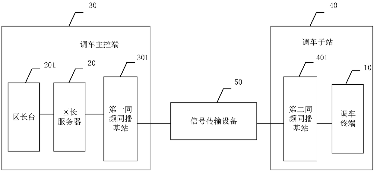
[0033] The embodiment of the invention discloses a railway plane shunting system, which achieves the purpose of uniformly managing the shunting operations of various railway stations and avoids waste of manpower and resources.

[0034] See figure 1 , figure 1 It is a schematic structural diagram of a railway level shunting system disclosed in the embodiment of the present invention. In this embodiment, one shunting sub-station is used for illustration, but it...


PUM


Abstract

The invention discloses a railway flat shunting system. Signal transmission equipment is used for transmitting signals in a first co-frequency multicast base station in a shunting main control end tosecond co-frequency multicast base stations of all shunting sub-stations, so that the purpose of signal interaction between the shunting main control end and each shunting sub-station is achieved. Then, after a target signal is sent from a zone length platform and a zone length server, the target signal is transmitted to the second co-frequency multicast base stations by the first co-frequency multicast base station, and finally, the second co-frequency multicast base stations are used for transmitting the target signal to shunting terminals. In this way, the shunting terminals can carry out shunting operation on stations corresponding to the shunting sub-stations according to the target signal. Therefore, the shunting operation of all the shunting sub-stations can be realized by the shunting main control end, so that the purpose of carrying out unified management on the shunting operation of each railway station is achieved, and waste of manpower and resources is avoided.

Description

technical field [0001] The invention relates to the technical field of railways, in particular to a railway plane shunting system. Background technique [0002] The shunting command of the railway station generally adopts a wireless digital flat shunting system with independent networking of a single station, simplex at the same frequency, and simultaneous transmission of several voices. Vehicle terminal, district chief platform and district chief server. The mayor's station and the district chief's server are located in the traffic room of the station signal building, and are responsible for sending shunting work orders to the shunting terminal, calling, monitoring and managing the operation of the station shunting yard. According to the shunting work order received, the shunting hand-held station issues shunting orders to the connecting hand-held station, and sends driving instructions to the machine controller according to the shunting information reported by the connect...

Claims


Application Information

Patent Timeline
IPC IPC(8): B61L27/00
CPCB61L27/70
Inventor 楼向东贾明献孙继康杨兴王俊岩周恒蔡学利李强王伟
Owner 兖矿能源集团股份有限公司
Why Eureka
Try Eureka