Rubber pipe conveying and unwinding machine

A technology of rubber tube and coiler, applied in the rubber field, can solve the problems of less rubber tube and full reel, and achieve the effect of convenient disassembly, improved efficiency, and convenient use of the rubber tube conveying and unwinding machine.

Pending Publication Date: 2018-11-13
NANJING HUI LONG RUBBER PROD CO LTD
View PDF9 Cites 2 Cited by
  • Summary
  • Abstract
  • Description
  • Claims
  • Application Information

AI Technical Summary

Problems solved by technology

[0002] At present, in rubber processing factories, in order to store rubber tubes, rubber tube unwinding and unwinding machines are often used to unwind rubber tubes, but the existing rubber tube unwinding and unwinding machines not only unwind very few rubber tubes each time , and when the rubber tube is being unrolled, the reel is often full, but there are still many cases of rubber tubes, which require the staff to manually cut the rubber tube. Therefore, we propose a rubber tube unwinding machine

Method used


Image

  • Rubber pipe conveying and unwinding machine
  • Rubber pipe conveying and unwinding machine

Examples


Embodiment Construction

[0014] In order to make the technical means, creative features, goals and effects achieved by the present invention easy to understand, the present invention will be further described below in conjunction with specific embodiments.

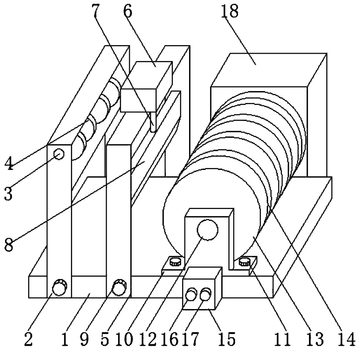
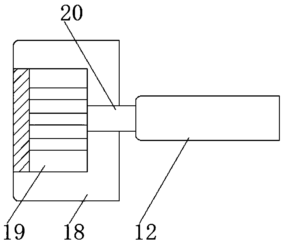
[0015] Such as Figure 1-2 As shown, a rubber tube feeding and unwinding machine includes a machine base 1, a second support frame 5 and a working power supply 15, a first support frame 2 is installed on the left side of the top of the machine base 1, and the first support frame 2 A first rotating shaft 3 is installed on the inner upper end, a pulley 4 is installed on the outside of the first rotating shaft 3, a second supporting frame 5 is installed on the right side of the first supporting frame 2, and a cylinder is installed in the middle of the top of the second supporting frame 5 6. The bottom of the cylinder 6 is connected to the cutting rod 7 through the second support frame 5, the bottom of the cutting rod 7 is connected to the cutting kni...


PUM


Abstract

The invention discloses a rubber pipe conveying and unwinding machine. The rubber pipe conveying and unwinding machine comprises a machine base, a second supporting frame and a winding wheel; a firstsupporting frame is installed on the left side of the top of the machine base; a first rotary shaft is installed at the upper end of the inner side of the first supporting frame; a pulley is installedon the outer side of the first rotary shaft; a second supporting frame is installed on the right side of the first supporting frame; a cylinder is installed in the middle of the top of the second supporting frame; the bottom of the cylinder is connected with a cutting rod through the second supporting frame; a cutter is connected to the bottom of the cutting rod; and the second supporting frame is located on the top of the machine base. By means of the pulley on the first supporting frame and a pipe groove in the winding wheel, four rubber pipes can be unwound on the machine at a time, and the rubber pipe unwinding efficiency is greatly improved; by arranging the cylinder and the cutter on the second supporting frame, the rubber pipes can be cut off when the winding wheel is full but theleft portions of the rubber pipes are still very long, the manual artificial cut-off process is omitted, and the rubber pipe conveying and unwinding machine is relatively practical and suitable for being widely used and popularized.

Description

technical field [0001] The invention relates to the field of rubber, in particular to a rubber tube feeding and unwinding machine. Background technique [0002] At present, in rubber processing factories, in order to store rubber tubes, rubber tube unwinding and unwinding machines are often used to unwind rubber tubes, but the existing rubber tube unwinding and unwinding machines not only unwind very few rubber tubes each time , and when the rubber tube is being unrolled, the reel is often full, but there are still many cases of the rubber tube, which requires the staff to manually cut the rubber tube. Therefore, we propose a rubber tube unwinding machine. Contents of the invention [0003] The main purpose of the present invention is to provide a rubber tube feeding and unwinding machine, which can effectively solve the problems in the background technology. [0004] In order to achieve the above object, the technical scheme that the present invention takes is: [0005]...

Claims


Application Information

Patent Timeline
Patent Type & Authority Applications(China)
IPC IPC(8): B65H49/32B65H49/20
CPCB65H49/20B65H49/32B65H2701/33
Inventor 徐祥王祥慈
Owner NANJING HUI LONG RUBBER PROD CO LTD
Why Eureka
Try Eureka