Winding device

A technology of winding device and spool, applied in the field of mechanical processing, can solve the problems of excessive tension, excessive relaxation, affecting the winding process, etc., and achieve the effect of occupying a reasonable space

Inactive Publication Date: 2018-11-13
黄丽红 +1
View PDF0 Cites 4 Cited by
  • Summary
  • Abstract
  • Description
  • Claims
  • Application Information

AI Technical Summary

Problems solved by technology

For example, the wire on the bobbin is wound unevenly in the axial direction of the bobbin, because the wire will be pulled from a fixed position of the bobbin, which will cause a certain section of the bobbin to overwrap the wire, instead of making full use of the entire axial direction for uniform winding; In addition, the wire on the winding shaft will be in an over-tensioned or over-slack state during the traction process, resulting in disordered wires or broken wires, which will affect the entire winding process.

Method used


Image

  • Winding device
  • Winding device
  • Winding device

Examples


Embodiment 1

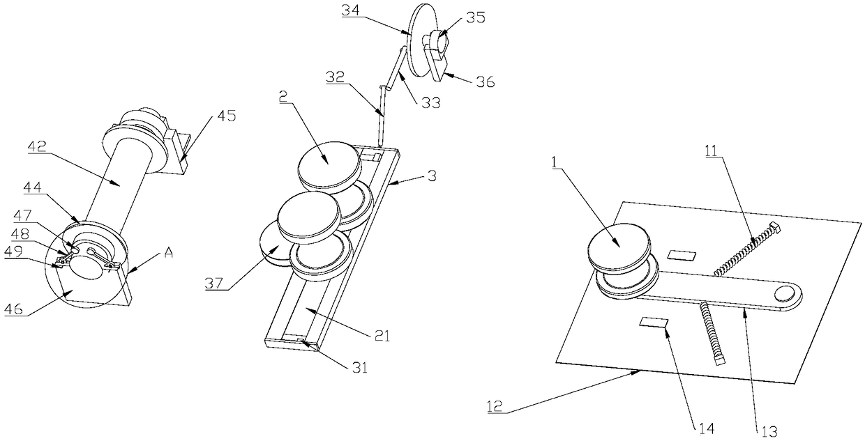
[0035] Such as figure 2 , A winding device, comprising a buffer wheel 1, a layer winding wheel 2 and a spool 4 arranged at intervals in sequence;

[0036] The buffer wheel 1 is arranged vertically, the bottom of the buffer wheel 1 is rotatably connected to one end of the buffer rod 13, and the other end of the buffer rod 13 is hinged to the buffer frame 12; both sides of the buffer rod 13 are respectively connected to the buffer spring 11 , The other side of the buffer spring 11 is connected to the buffer frame 12;

[0037] Two vertically arranged layer winding wheels 2 are arranged side by side. The bottom of the layer winding wheel 2 is rotatably connected to an adjusting rod 21, and the adjusting rod 21 is movably connected to the reciprocating seat 3, and the reciprocating seat 3 is provided with an adjusting wheel 23. The outer peripheral wall of the adjusting wheel 23 is provided with teeth 22, and the adjusting rod 21 and the adjusting wheel 23 are provided with a rack 24 t...

Embodiment 2

[0043] Such as figure 2 , image 3 with Figure 4 On the basis of including embodiment 1, the spool 4 is arranged horizontally, the two ends of the spool 4 are respectively connected to the movable support 46 and the fixed support 45 in rotation, and the spool 4 at one end of the fixed support 45 is connected to the spool motor, so The spool motor is fixed on the spool motor base, and the spool motor base is connected to the fixing bracket 45.

[0044] Both ends of the spool 4 are provided with a movable support 46 and a fixed support 45 to facilitate the replacement of the fully wound spool 4; a spool motor is installed on one side of the fixed support 45, which plays a role in the stability of the equipment, and the production safety performance is higher than that of the movable support. 46 side.

[0045] The upper part of the movable support 46 is provided with a spool accommodating groove, the other end of the spool 4 is overlapped in the spool accommodating groove, and the ...

Embodiment 3

[0054] Such as figure 1 with figure 2 , On the basis of including embodiment 1, the buffer racks 12 on both sides of the buffer rod 13 are respectively provided with induction detectors 14.

[0055] When the wire tension is too tight or broken, the buffer frame 12 will over-rotate. In order to avoid safety accidents, an induction detector 14 is set at a suitable position. When a danger occurs, the induction detector 14 senses the buffer frame 12. Then stop operation and improve safety performance.


PUM


Abstract

The invention provides a winding device. The winding device comprises a buffering wheel, layer winding wheels and a wire shaft. The buffering wheel is vertically arranged, the bottom of the bufferingwheel is rotationally connected to one end of a buffering rod, and the other end of the buffering rod is hinged to a buffering frame. The two sides of the buffering rod are connected with buffering springs correspondingly, and the other sides of the buffering springs are connected with the buffering frame; the two vertically-arranged layer winding wheels are arranged side by side, the bottoms of the layer winding wheels are rotationally connected to an adjusting rod, the adjusting rod is movably connected to a reciprocating base, the reciprocating base is provided with an adjusting wheel, teeth are arranged on the periphery wall of the adjusting wheel, and the side, close to the adjusting wheel, of the adjusting rod is provided with a rack engaged with the teeth. According to the winding device, wire disorder or wire snap can be prevented, wires can be evenly wound around the wire shaft, and the effects that the space utilization rate is high, and the production efficiency is high areachieved.

Description

Technical field [0001] The invention belongs to the field of mechanical processing, and in particular relates to a wire winding device. Background technique [0002] Whether it is during production or use, the disorderly placement of multiple wires or cables will make the site very messy, affect the cleanliness of the ground, and cause safety risks in the production workshop. The winding device has become an important device that rolls the wire into a coil for transportation and storage. [0003] A general winding device is composed of a motor, a reel, a spool, and a base. Although this general winding device solves the space occupation problem and sorts out the storage of linear materials, there are still some problems. For example, the wire on the spool is wound unevenly in the axial direction of the spool, because the wire will be drawn from a fixed position of the spool, which will cause a certain section of the spool to over-wind the wire instead of making full use of the ent...

Claims


Application Information

Patent Timeline
Patent Type & Authority Applications(China)
IPC IPC(8): B65H54/553B65H54/44B65H54/28B65H51/06B65H63/04B65H63/024
CPCB65H54/553B65H51/06B65H54/28B65H54/44B65H63/024B65H63/04B65H2701/34B65H2701/36
Inventor 黄丽红刘艳芳
Owner 黄丽红
Why Eureka
Try Eureka